Ultrasonic motor, and electronic timepiece having ultrasonic motor

An ultrasonic and motor technology, applied in the field of analog display electronic clocks, can solve problems such as difficulties, deterioration of oil quality, and increased sliding, and achieve excellent durability

Inactive Publication Date: 2005-04-06
KITAGAWA INDS +1
View PDF7 Cites 1 Cited by
  • Summary
  • Abstract
  • Description
  • Claims
  • Application Information

AI Technical Summary

Problems solved by technology

In particular, when a large amount of carbon black is added to the raw material resin, since the friction coefficient of the surface of the ultrasonic rotor decreases, the sliding of the contact surface between the ultrasonic rotor and the ultrasonic stator increases. Therefore, the spring force of the pressure spring is controlled to be Proper value is very difficult
In the case of oiling the contact surface between the ultrasonic rotor and the ultrasonic stator, the quality of the oil deteriorates due to long-term use, which shortens the maintenance time of the machine

Method used


Image

  • Ultrasonic motor, and electronic timepiece having ultrasonic motor
  • Ultrasonic motor, and electronic timepiece having ultrasonic motor
  • Ultrasonic motor, and electronic timepiece having ultrasonic motor

Examples


Embodiment Construction

[0029] (1) [Structure of Ultrasonic Motor]

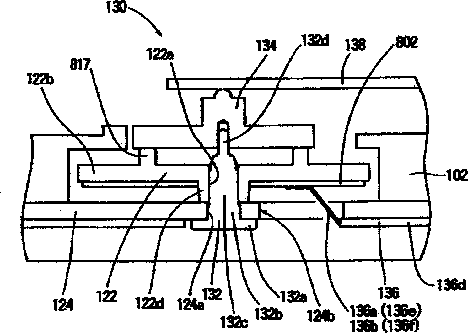
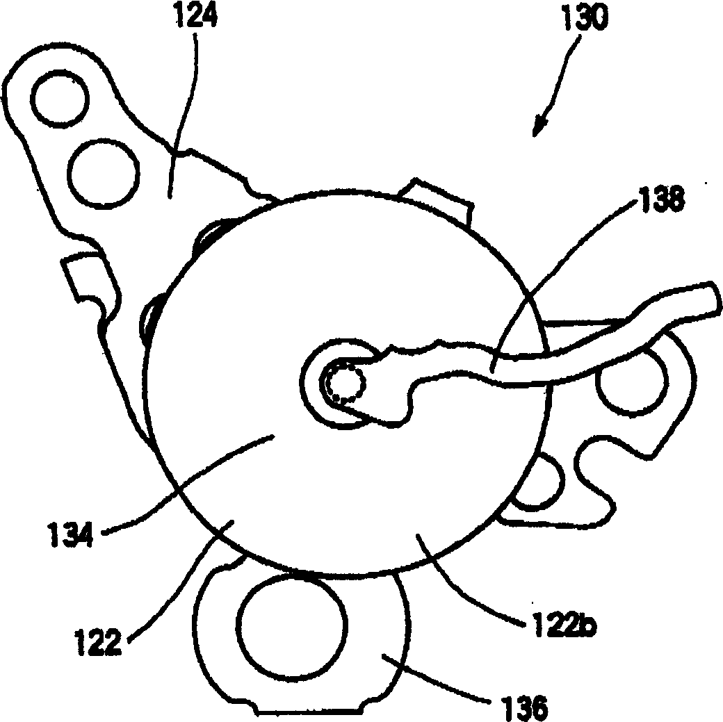
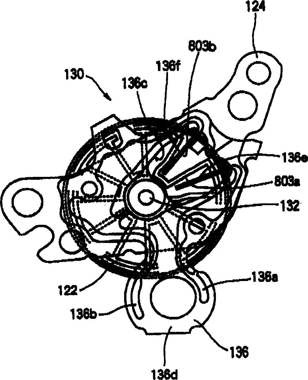
[0030] See attached Figure 1~3 , The ultrasonic motor 130 of the present invention is provided with an ultrasonic stator 122 , an ultrasonic motor support 124 , an ultrasonic motor shaft 132 , an ultrasonic rotor 134 , and an ultrasonic motor guide substrate 136 . The ultrasonic motor shaft 132 has a collar portion 132a, a first shaft portion 132b, a second shaft portion 132c, and a tip shaft portion 132d.

[0031] The ultrasonic motor support 124 has a first through hole 124a through which the ultrasonic motor shaft 132 passes, and a second through hole 124b through which the conduction structure of the ultrasonic motor guide substrate 136 passes. The ultrasonic motor support 124 is fixed to the first shaft portion 132b of the ultrasonic motor shaft 132 by passing the first through hole 124a through the ultrasonic motor shaft 132 . The lower surface of the ultrasonic motor support 124 is in contact with the collar portion 132 a ...


PUM


Abstract

The invention relates to an ultrasonic motor, an electronic timepiece, and an electronic apparatus, which includes an ultrasonic rotor formed from a base resin of thermoplastic resin. Moreover, the invention includes an ultrasonic rotor which contacts with an ultrasonic stator under pressure, the ultrasonic rotor being formed from a filler containing resin. Alternatively an electronic timepiece with the ultrasonic motor is constructed. Furthermore, an electronic apparatus with the ultrasonic motor which is constructed.

Description

technical field [0001] The present invention relates to an ultrasonic motor including an ultrasonic rotor formed of a raw material resin as a thermoplastic resin. In addition, the present invention also relates to an analog display type electronic clock having a display wheel rotated by rotation of an ultrasonic motor. In addition, the present invention also relates to an electronic device with an ultrasonic motor including a power supply, a vibration source, a control circuit, and an ultrasonic motor. Background technique [0002] see Figure 12 , The conventional ultrasonic motor 930 has an ultrasonic stator 922 , an ultrasonic motor support 924 , an ultrasonic motor shaft 932 , an ultrasonic rotor 934 , and an ultrasonic motor guide substrate 936 . The ultrasonic motor shaft 932 includes a collar portion 932a, a first shaft portion 932b, a second shaft portion 932c, and a tip shaft portion 932d. The ultrasonic motor support 924 has a first through hole 924a through whic...

Claims


Application Information

Patent Timeline
Patent Type & Authority Applications(China)
IPC IPC(8): G04C3/12H01L41/09H02N2/00H02N2/12
CPCG04C3/12H02N2/007H02N2/166
Inventor 远藤守信内山哲夫山口晃生近藤康雄青山宽重城幸一郎竹田和俊竹中雅人铃木重男所毅
Owner KITAGAWA INDS
Why Eureka
Try Eureka