Sealing device

A technology of sealing device and main seal, applied in the direction of engine seal, bearing, shaft, etc., can solve the problem of sealing characteristics without any elaboration, and achieve the effect of high friction characteristics

Inactive Publication Date: 2007-08-29
NOK CORP
View PDF2 Cites 4 Cited by
  • Summary
  • Abstract
  • Description
  • Claims
  • Application Information

AI Technical Summary

Problems solved by technology

[0004] In addition, although the following patent document 2 proposes a scheme of providing axial protrusions on the rough-finished part, in this patent document 2, it is mainly applicable to the case where the main seal lip has a two-layer seal lip structure. There is no explanation for the structure of the main seal lip being a single-layer seal lip without degrading the sealing performance

Method used


Image

  • Sealing device
  • Sealing device
  • Sealing device

Examples


no. 1 example

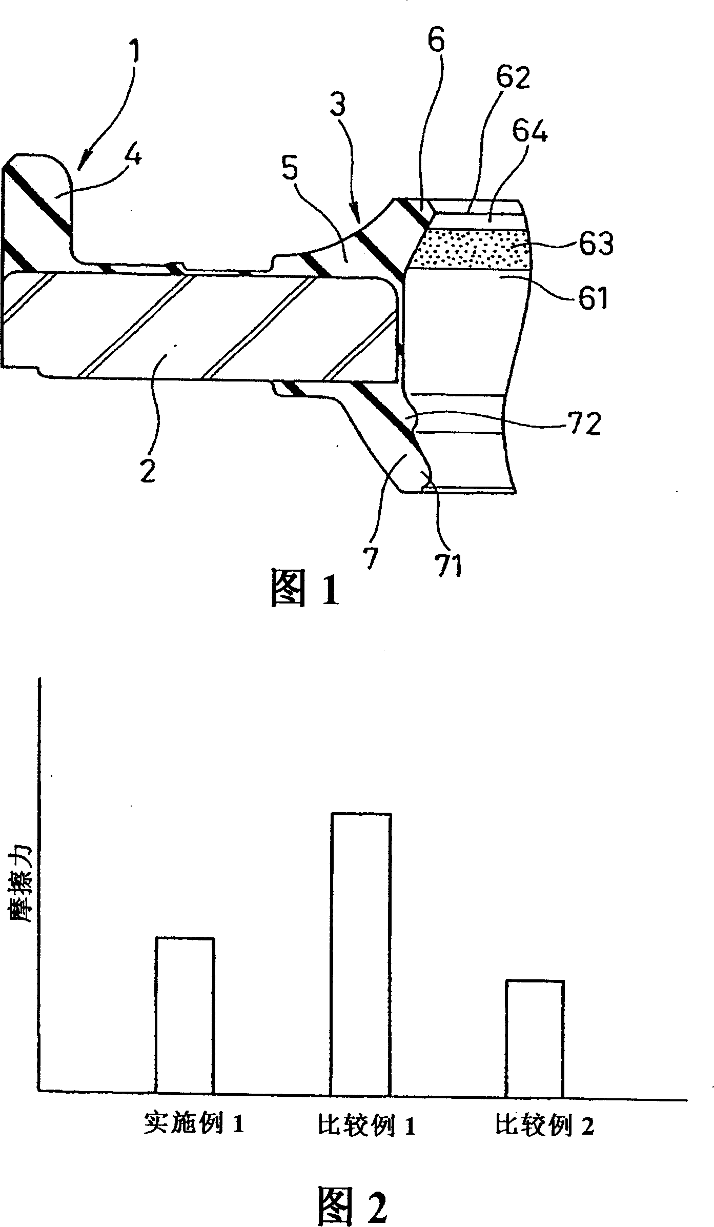
[0046] Fig. 1 shows a section of key parts of a sealing device 1 according to a first embodiment of the present invention, which has the following structure.

[0047] The sealing device 1 includes a metal ring 2 with a cross-sectional cylindrical shape, and a sealing body 3 that is vulcanized and bonded on the metal ring 2 and is composed of a rubber-like elastic body. The sealing body 3 integrally vulcanizes the fixed abutting part 4 and the sealing part 5 on the metal ring 2 . Among them, the fixed close part 4 is in close contact with the housing not shown in the figure located on the sealing object side (inner side) on the outer peripheral side of the metal ring 2; The shaft is snug and slidable. The seal part 5 is composed of a main seal lip 6 and a dustproof seal lip 7. The main seal lip 6 is located on the inner side of the metal ring 2 and extends toward the inner side. Structure, the dust-proof sealing lip 7 is located on the outer side of the metal ring 2 and exten...

no. 2 example

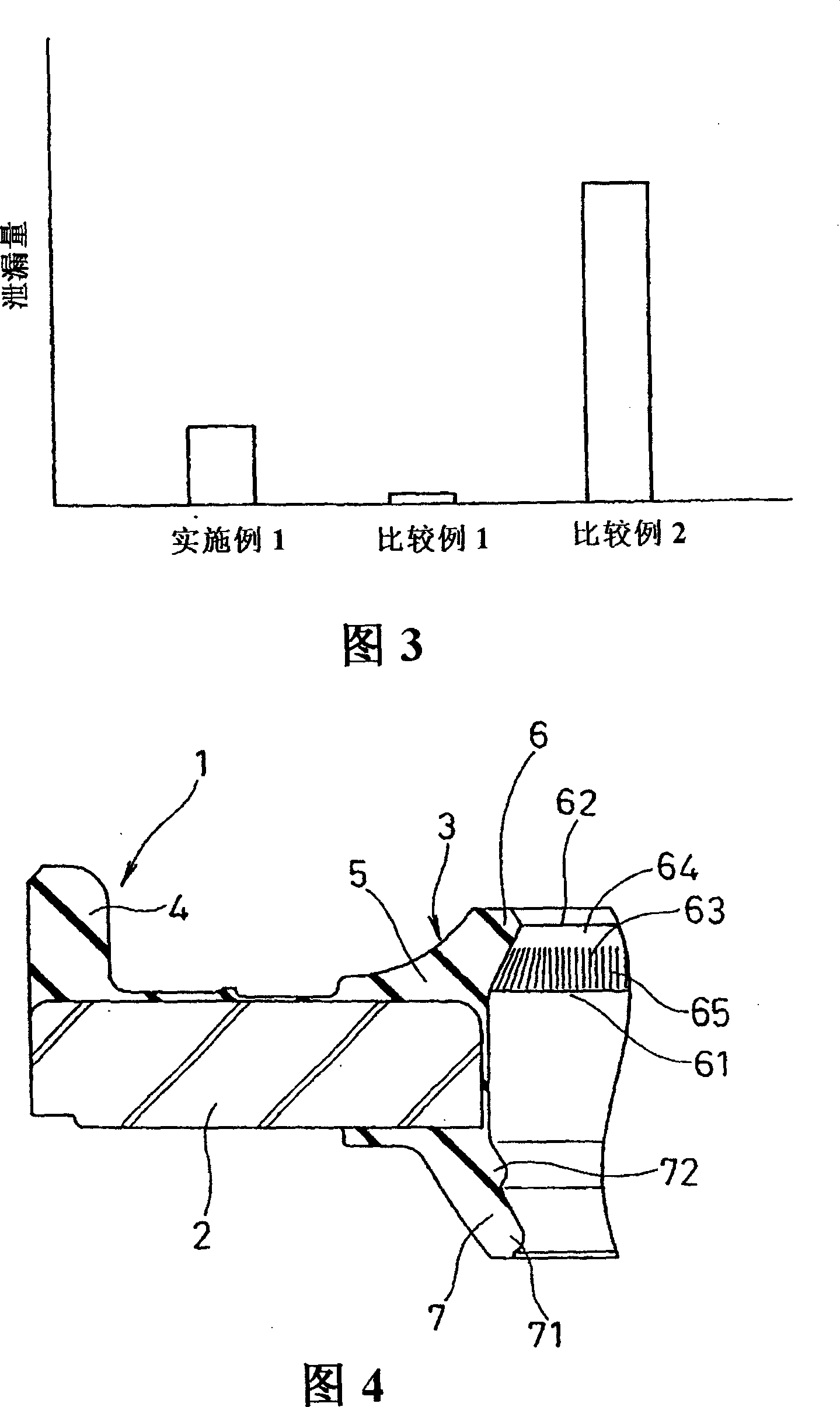
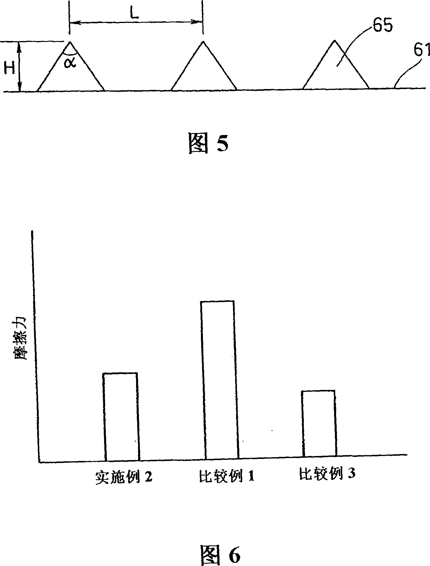
[0059] Fig. 4 shows the cross-section of key parts of the sealing device 1 according to the second embodiment of the present invention, and Fig. 5 is a cross-sectional view for explaining the projection shape image formed on the sliding surface of the main sealing lip in Fig. Different parts of the first embodiment.

[0060] In the second embodiment, on the sliding surface 61 of the main sealing lip 6 at a predetermined distance from the lip 62 , a plurality of protrusions 65 extending in the axial direction are arranged at equal intervals to cover the entire circumference. That is, the protrusion 65 parallel to the axial direction is provided on the rough-finished part 63 formed on the sliding surface 61 . Thus, between a set distance from the lip 62 to the protrusion 65 , a flat portion 64 is formed on which no concavo-convex portion is provided on the surface.

[0061] The protrusion 65 should be formed at a position 0.2 to 1 mm away from the lip 62 , preferably 0.3 to 0.7...

no. 3 example

[0071] Fig. 8 shows the section of key parts of the sealing device 1 according to the third embodiment of the present invention, and only the parts different from the first and second embodiments will be introduced below.

[0072] In the third embodiment, on the sliding surface 61 of the main sealing lip 6 at a position with a set distance from the lip 62, a plurality of arc-shaped notches 67 extending in the axial direction are arranged at equal intervals on the entire peripheral surface superior. That is, the rough-worked portion 63 formed on the sliding surface 61 is provided with a plurality of boat-shaped notches 67 parallel to the axial direction. Thus, between a set distance from the lip 62 to the boat-shaped notch 67, a flat portion 64 on which no concavo-convex portion is provided on the surface is formed.

[0073] In the case of configuring the sealing device 1 of the third embodiment having the above-mentioned structure, the sliding surface 61 of the main seal lip ...


PUM


Abstract

A sealing device (1), wherein a main seal lip (6) used for a shock absorber is formed in a one-stage seal lip structure to improve friction characteristics while securing sealing performance. A roughened portion (63) to which satin finishing is applied to form irregularities on the surface thereof is formed on the sliding surface (61) of the main seal lip (6) slidably moving on a mating member at a position apart a specified distance from a lip edge (62). An area between the lip edge (62) and the portion where the roughened portion (63) is formed is formed in a plane portion (64) to which the satin finishing for forming irregularities is not applied. In place of the satin finishing, a plurality of axially extending projections (65), concave threads (67), or lattice-shaped projections (68) may be formed on the roughened portion.

Description

technical field [0001] The present invention relates to a sealing device, and specifically relates to a sealing device in which a main seal lip used in a shock absorber has a single-layer seal lip structure. Background technique [0002] In recent years, an oil seal, which is a sealing device used in a shock absorber, has been required to improve its friction characteristics (lower friction) in addition to the improvement of the sealing characteristics. Generally, an oil seal consisting of a main seal lip and a dust seal lip of a 2-layer lip structure is used in a shock absorber. In this case, as described in Patent Document 1, the friction characteristics are improved by satin-finishing, providing notches, parallel protrusions, and the like on the second layer of the main lip seal. By providing unevenness on the sliding surface of the second seal lip, a space where an oil film exists is formed, and the friction characteristics are improved. However, when it is applied to a...

Claims


Application Information

Patent Timeline
Patent Type & Authority Applications(China)
IPC IPC(8): F16J15/32F16F9/36F16J15/324F16J15/3252
CPCF16C33/7823F16F9/36F16J15/3232F16J15/324F16C2240/54F16J15/32
Inventor 佐藤博幸渡边胜水野谷弘一大谷刚生新井秀德伊东聪祐大久保良太
Owner NOK CORP
Why Eureka
Try Eureka