Frame needle bar for knitting frame, especially tricot machine

A warp knitting machine and knitting machine technology, applied to knitting machines, can solve the problems of not having special design gaps and pressure plates, and achieve the effects of constant orientation, uniform working process, and high needle pitch stability

Active Publication Date: 2005-04-27
KARL MAYER STOLL R&D GMBH
View PDF4 Cites 3 Cited by
  • Summary
  • Abstract
  • Description
  • Claims
  • Application Information

AI Technical Summary

Problems solved by technology

With this construction method, there is no specially designed gap pressure plate, so it does not have the advantages of using two materials.

Method used


Image

  • Frame needle bar for knitting frame, especially tricot machine
  • Frame needle bar for knitting frame, especially tricot machine
  • Frame needle bar for knitting frame, especially tricot machine

Examples


Embodiment Construction

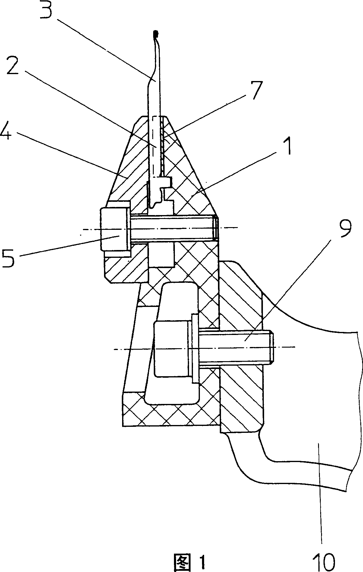
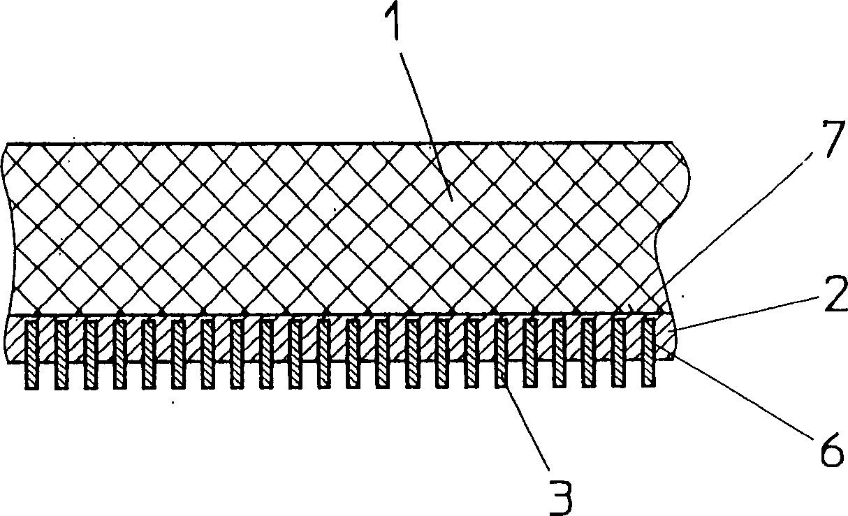
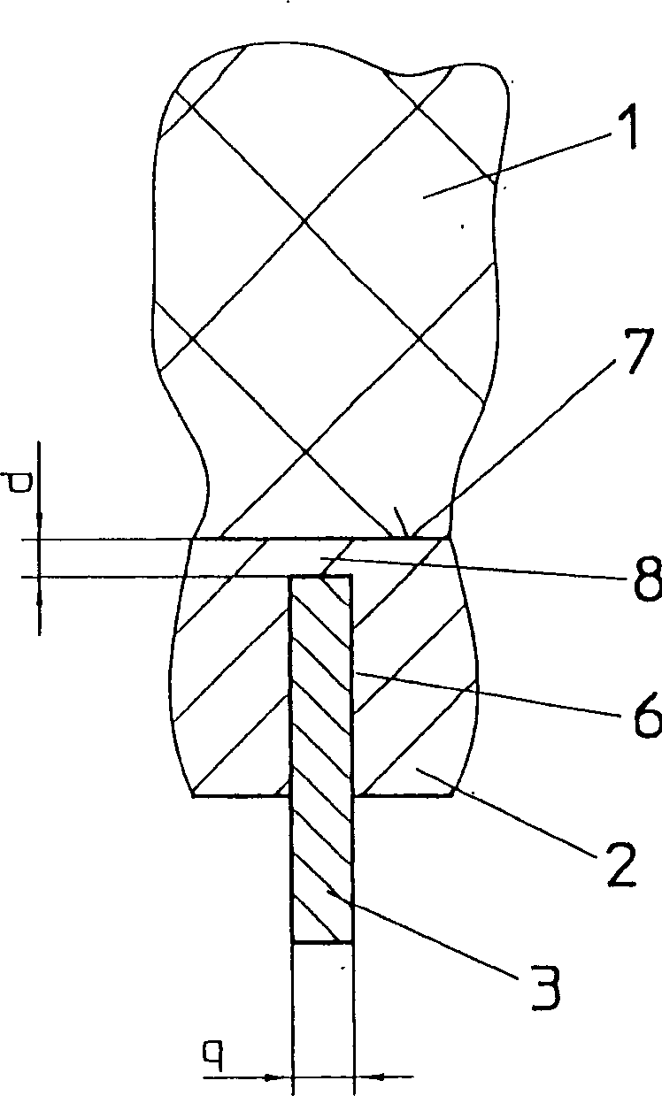
[0021] FIG. 1 shows the base body 1 of the hollow needle bed. Its structure is known, so it will not be repeated here. The base body 1 of the needle bed consists of carbon-fibre-reinforced plastic and is rigid and resistant to deformation. A gap pressure plate 2 is fixed on the base body 1 of the needle bed. The gap pressure plate 2 is, for example, glued with its contact surface 7 to the basic body 1 of the needle bed. The gap pressure plate 2 extends over the entire working width of the needle bed and has figure 2 and 3 The illustrated receiving groove 6 extends perpendicularly to its longitudinal direction. The knitting mechanism 3 is embedded in the accommodating groove 6 by its fixed end. In the embodiment shown in FIG. 1 , the fixed pressing plate 4 is used to hold and fix the fixed end of the knitting mechanism 3 in the accommodating groove 6 under the force of the clamping bolt 5 . In this example the knitting element 3 is a knitting needle.

[0022] The basic b...


PUM


Abstract

The present invention relates to neilsbed for a warp knitting machine, which base body (1) is composed of plastics with reinforced carbon fiber and couples with a gap gripper (2). The contact surface (7) of the gap gripper (2) couples with the base body (1) of the neilsbed and has a reception groove (6), where a wreathe work (3) is embedded. The gripper foot (8) has a thickness of d which is smaller than the transverse size q of the wreathe work (3). Thus, to absorb reliably thermal stress within the contact surface (7), the gap gripper (20 will not occur thermal expansion corresponding to the base body (1) of the neilsbed.

Description

technical field [0001] The invention relates to a needle bed of a knitting machine, in particular a warp knitting machine, having a base body of the needle bed made of carbon-fibre-reinforced plastic, with a metal gap pressure plate with a structure for accommodating a looper The accommodating groove at the end of the piece has a contact surface that fits with the base of the needle bed and is fixedly connected with the base of the needle bed, wherein the accommodating groove extends vertically to the longitudinal direction of the gap pressing plate. Background technique [0002] Such a needle bed belongs to the known prior art, for example disclosed in DE 411108A1. The basic body of the needle bed is, for example, a hollow profile made of carbon-fibre-reinforced plastic, the interior of which is reinforced by a profile made of rigid foam. Gap pressure plates are known to be produced from a lightweight metal, in particular aluminum or an aluminum alloy. The gap pressing pl...

Claims


Application Information

Patent Timeline
Patent Type & Authority Applications(China)
IPC IPC(8): D04B27/06
CPCD04B27/06
Inventor 鲁迪·维尔特
Owner KARL MAYER STOLL R&D GMBH
Why Eureka
Try Eureka