High pressure container and manufacture thereof

A high-pressure vessel and metal technology, which is applied in the manufacture of vessel structures, pressure vessels, and outer walls of vessel structures, etc., can solve the problem of fatigue of metal linings, and achieve the effect of preventing axial sliding and preventing radial sliding.

Inactive Publication Date: 2005-04-27
TOYOTA JIDOSHA KK
View PDF1 Cites 18 Cited by
  • Summary
  • Abstract
  • Description
  • Claims
  • Application Information

AI Technical Summary

Problems solved by technology

[0003] In a high-pressure vessel with a metal liner, there is a problem of fatigue of the metal liner caused by expansion / contraction of the vessel with gas filling and discharge
On the other hand, if the amount of fiber in the composite housing is reduced for weight reduction and cost reduction, the amount of expansion / contraction will increase, thereby limiting the number of allowable filling / draining

Method used


Image

  • High pressure container and manufacture thereof
  • High pressure container and manufacture thereof
  • High pressure container and manufacture thereof

Examples


no. 1 Embodiment

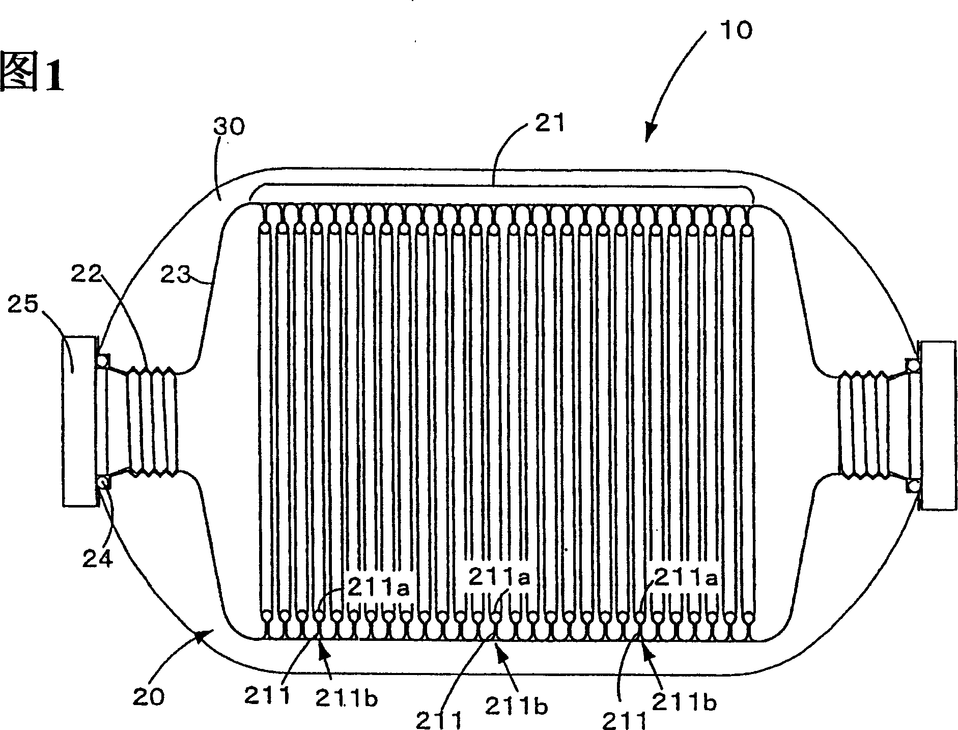
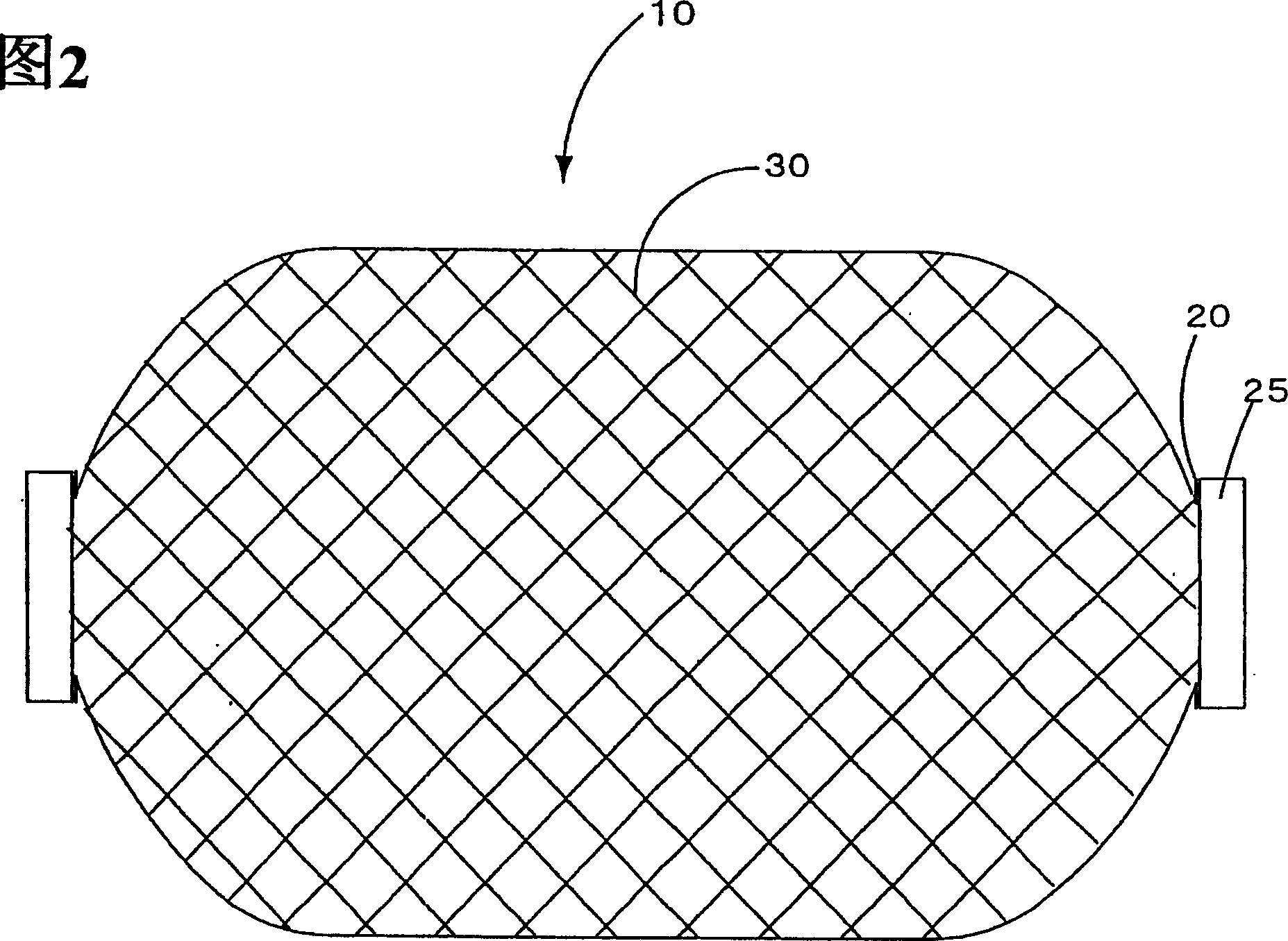
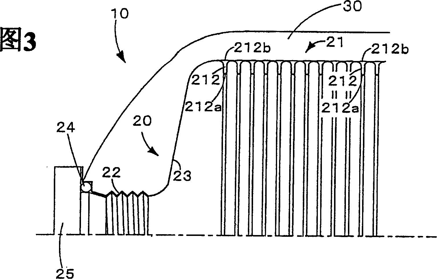
[0060] A high-pressure container according to a first embodiment will be described with reference to FIGS. 1 to 3 . FIG. 1 is an explanatory diagram showing a part in cross-section for explaining the inside of a high-pressure vessel according to the first embodiment. Fig. 2 is an explanatory view showing the appearance of the high-pressure container according to the first embodiment. Fig. 3 is an explanatory view showing a first modified example of the high-pressure container according to the first embodiment.

[0061] The high-pressure container 10 related to the first embodiment has a cylindrical shape as shown in FIG. 2 . In addition, as shown in FIG. Composite shell 30 formed on the outer periphery of the As the metal liner 20, for example, stainless steel, aluminum, or the like can be used.

[0062] The metal liner 20 has a cylindrical body portion 21 , joint portions 22 at both ends, and a cover portion 23 connecting the body portion 21 and the joint portions 22 . Th...

no. 2 Embodiment

[0071] refer to Figure 4 ~ Figure 12 The high-pressure container according to the second embodiment will be described. Figure 4 It is a detailed view showing the inside of the high-pressure vessel according to the second embodiment in detail. Figure 5 It is an explanatory diagram showing a first modified example of the high-pressure container according to the second embodiment. Figure 6 It is an explanatory diagram showing a second modified example of the high-pressure container according to the second embodiment. Figure 7 It is an explanatory diagram showing a third modified example of the high-pressure container according to the second embodiment. Figure 8 It is an explanatory diagram showing a fourth modified example of the high-pressure container according to the second embodiment. Figure 9 It is an explanatory diagram showing a fifth modified example of the high-pressure container according to the second embodiment. Figure 10 It is a flowchart showing the manuf...

no. 3 Embodiment

[0086] A high-pressure container according to a third embodiment will be described with reference to FIG. 14 . Fig. 14 is a detailed view showing the interior of the high-pressure container according to the third embodiment. The metal liner 50 of the high-pressure vessel 12 according to the third embodiment is composed of a main body member 52 integrally formed with a helical groove functioning as an expansion and contraction allowing portion and constituting a main body 51, and an opposed main body member. 52 are screwed together to form an end member 53 . In addition, the other components of the high-pressure vessel 12 according to the third embodiment are the same as those of the high-pressure vessel 10 according to the first embodiment, so the same reference numerals are assigned and descriptions thereof are omitted.

[0087] According to the high-pressure vessel 12 according to the third embodiment, since the metal lining 50 can be formed by screwing the end member 53 to...


PUM


Abstract

A high pressure tank 10 comprises a metal liner 20 having a desired tank shape; and a composite material shell 30 formed on the periphery of the metal liner 20 . The metal liner 20 comprises a cylindrical barrel portion 21 , a mouthpiece 22 located at each of two end portions, and a cap portion 23 connecting barrel portion 21 with mouthpiece 22 . Extensible portions 211 of bellows configuration are formed along the entire length of the metal liner 20 in the axial (lengthwise) direction. The extensible portions 211 impart elastic action through opening and closing (deformation) of their basal portions 211 b, thereby preventing slippage from occurring between the metal barrel portion 21 and the composite material shell 30 when the high pressure tank 10 expands and contracts.

Description

technical field [0001] The invention relates to a high-pressure container made of composite material and a manufacturing method of the high-pressure container. Background technique [0002] As a high-pressure vessel that mainly stores gas, a high-pressure vessel that replaces the existing steel with a composite outer shell covered with a metal inner liner is practically used. [0003] In a high-pressure vessel using a metal liner, there is a problem of fatigue of the metal liner caused by expansion / contraction of the vessel with gas filling and discharge. On the other hand, reducing the amount of fiber in a composite casing for weight reduction and cost reduction will increase the amount of expansion / contraction, thereby limiting the number of allowable filling / draining times. [0004] Therefore, there has been proposed a pressure vessel in which a part of the metal liner has a curved portion that moderates axial fluctuations caused by internal pressure fluctuations (see Pa...

Claims


Application Information

Patent Timeline
Patent Type & Authority Applications(China)
IPC IPC(8): F17C1/04B29C70/16B29C70/68B29L22/00F17B1/26F17C1/00F17C1/02F17C1/14F17C1/16
CPCY02E60/321F17C2260/011F17C2203/0619F17C2209/23F17C2203/0673F17C2203/0663F17C2203/067F17C2203/0621F17C2201/056F17C2223/035F17C2201/058F17C2201/054F17C2203/0607F17C1/14F17C2205/0397F17C2203/0643F17C2205/0323F17C2201/0104F17C2270/0168F17C2209/2109F17C2201/0109F17C2209/2154F17C2223/036F17B1/26F17C2203/0636F17C2221/012F17C2203/0646F17C2209/221F17C1/16F17C2209/22F17C2201/0195F17C2203/0604Y02E60/32F17C1/02
Inventor 金原雅彦森大五郎都筑诚熊野明子
Owner TOYOTA JIDOSHA KK
Why Eureka
Try Eureka