Intelligent long-distance maintaining bus system for vehicles and boats
A technology of remote maintenance and bus system, which is applied in vehicle maintenance/repair, vehicle maintenance, registration/instruction of vehicle operation, etc. It can solve problems affecting the use of other devices, high after-sales service costs, waste of power resources, etc., to prevent circuit Effects of fire prevention, easy wiring and maintenance, and simplified wiring harness
- Summary
- Abstract
- Description
- Claims
- Application Information
AI Technical Summary
Problems solved by technology
Method used
Image
Examples
Embodiment 1
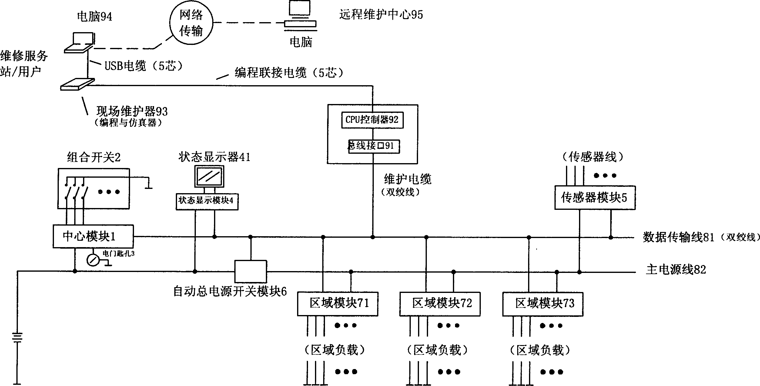
[0028] Embodiment one, see figure 1As shown, a vehicle and ship intelligent remote maintenance bus system of the present invention includes a central module 1, and the function of the central module 1 is to analyze and process input signals, and output corresponding control signals according to the processing results, and control the entire device. Realize the function of controlling and coordinating the work of each module; one or several combination switches 2, there are several switch keys in the combination switch 2, and the function of the combination switch 2 is to generate corresponding switches through the operation actions of each switch key The signal is input to the central module 1, and the corresponding control signal is output by the central module 1; a switch keyhole 3, the function of the switch keyhole 3 is to realize the power on and control of the central module 1 through the operation action of opening or closing the key. No control, and realize the control...
Embodiment 2
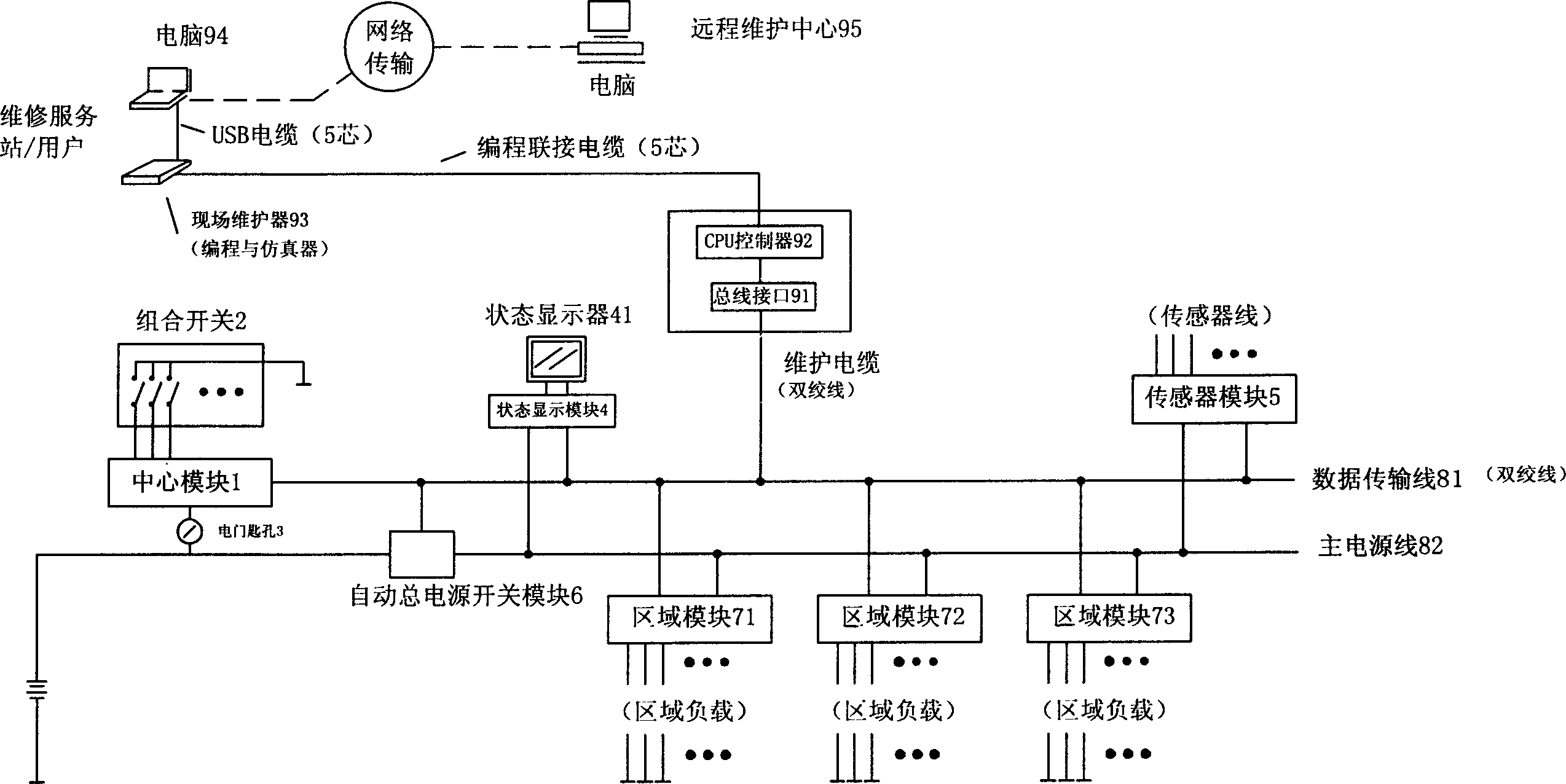
[0031] Embodiment two, see figure 2 As shown, a vehicle and ship intelligent remote maintenance bus system of the present invention is different from Embodiment 1 in that the switch keyhole 3 used to control the power supply of the control center module 1 is directly connected to the power input of the center module 1 Between terminal and total power supply output terminal, the opening gear of switch keyhole 3 makes the output of total power supply directly connect the power supply terminal of central module 1. The power input of the status display module 4 is controlled by the automatic main power switch module 6 , and the power input end of the status display module 4 is connected to the output of the automatic main power switch module 6 at this time.
PUM
 Abstract
Description
Claims
Application Information
 - R&D
- Intellectual Property
- Life Sciences
- Materials
- Tech Scout
- Unparalleled Data Quality
- Higher Quality Content
- 60% Fewer Hallucinations
Browse by: Latest US Patents, China's latest patents, Technical Efficacy Thesaurus, Application Domain, Technology Topic, Popular Technical Reports.
© 2025 PatSnap. All rights reserved.Legal|Privacy policy|Modern Slavery Act Transparency Statement|Sitemap|About US| Contact US: help@patsnap.com


