
Adjusting apparatus for a bicycle brake control device

A control device and brake technology, which is applied to bicycle brakes, brake transmission devices, bicycle control systems, etc., can solve the problem of not completely ensuring the stroke of the brake wire, and achieve the effect of ensuring the stroke.

Inactive Publication Date: 2005-05-04
SHIMANO INC
View PDF1 Cites 4 Cited by
  • Summary
  • Abstract
  • Description
  • Claims
  • Application Information

AI Technical Summary

Problems solved by technology

Therefore, according to the method of adjusting the initial position of the brake release, it may not be possible to fully ensure the stroke of the brake wire.

Method used


Image

  • Adjusting apparatus for a bicycle brake control device
  • Adjusting apparatus for a bicycle brake control device
  • Adjusting apparatus for a bicycle brake control device

Examples


no. 1 Embodiment

[0031] [the whole frame]

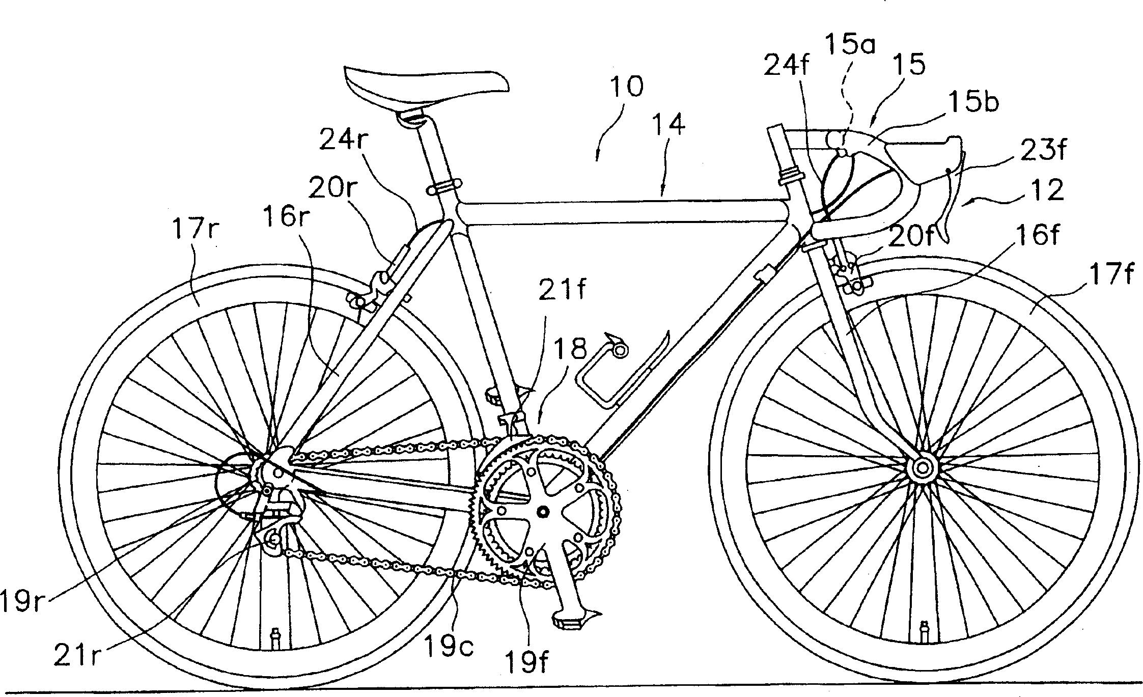
[0032] figure 1 Shown is a bicycle 10 equipped with a first embodiment of the present invention. Such a bicycle 10 is well known in this technical field, and a detailed description of the components of the bicycle will be omitted.

[0033] Bicycle 10 is a known off-road bicycle in the past, comprising: a bicycle frame 14 with handlebar 15, front fork and rear fork 16f, 16r; front and rear wheels 17f, 17r; The driving device 18 of the clamp (デイレ-ラ) 21f, 21r; the braking system 12.

[0034] The handlebar 15 is a general downturn type handlebar, and has: a central portion 15a extending in a left-right direction substantially perpendicular to the advancing direction of the bicycle 10; A pair of bent portions 15b whose bent front ends are bent downward.

[0035] The brake system 12 has: front and rear brake devices 20f, 20r installed on the front fork and rear fork 16f, 16r; front and rear brake operating mechanisms 23f, 23r ( Only the front brake op...

no. 2 Embodiment

[0058] In the above-mentioned first embodiment, although the brake release initial position can be adjusted to one position by the adjustment member 32, it may be adjusted to any position.

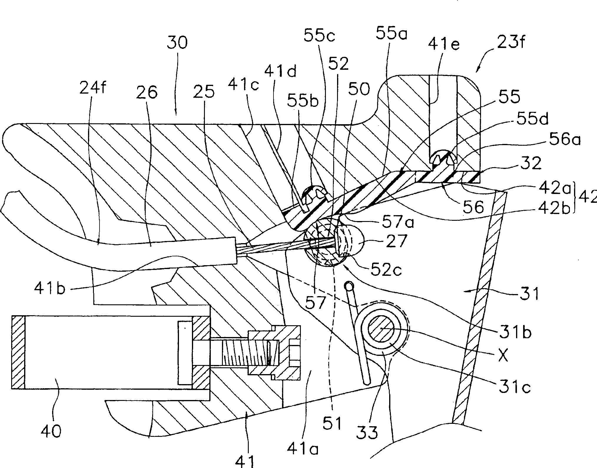
[0059] In Fig. 7, the adjustment mechanism (an example of the adjustment part) 132 of the brake operating mechanism 123f has: an adjustment body part 155 made integral with the brake bracket 130; The 1st position adjustment part 156; The 2nd position adjustment part 157 which has the adjustment nut 157a screwed to the adjustment bolt 156a, and the cam member 157b engaged with the adjustment nut 157a.

[0060] As shown in FIG. 8, the adjustment main body part 155 has the 1st shaft support part 155a and the 2nd shaft support part 155b which are coaxial at the upper part of the bracket main body 14 with a certain space|interval. Moreover, it also has the nut accommodating part 155c which accommodates the adjustment nut 157a non-rotatably but freely movable in the axial direction. A flanged n...


PUM


Abstract

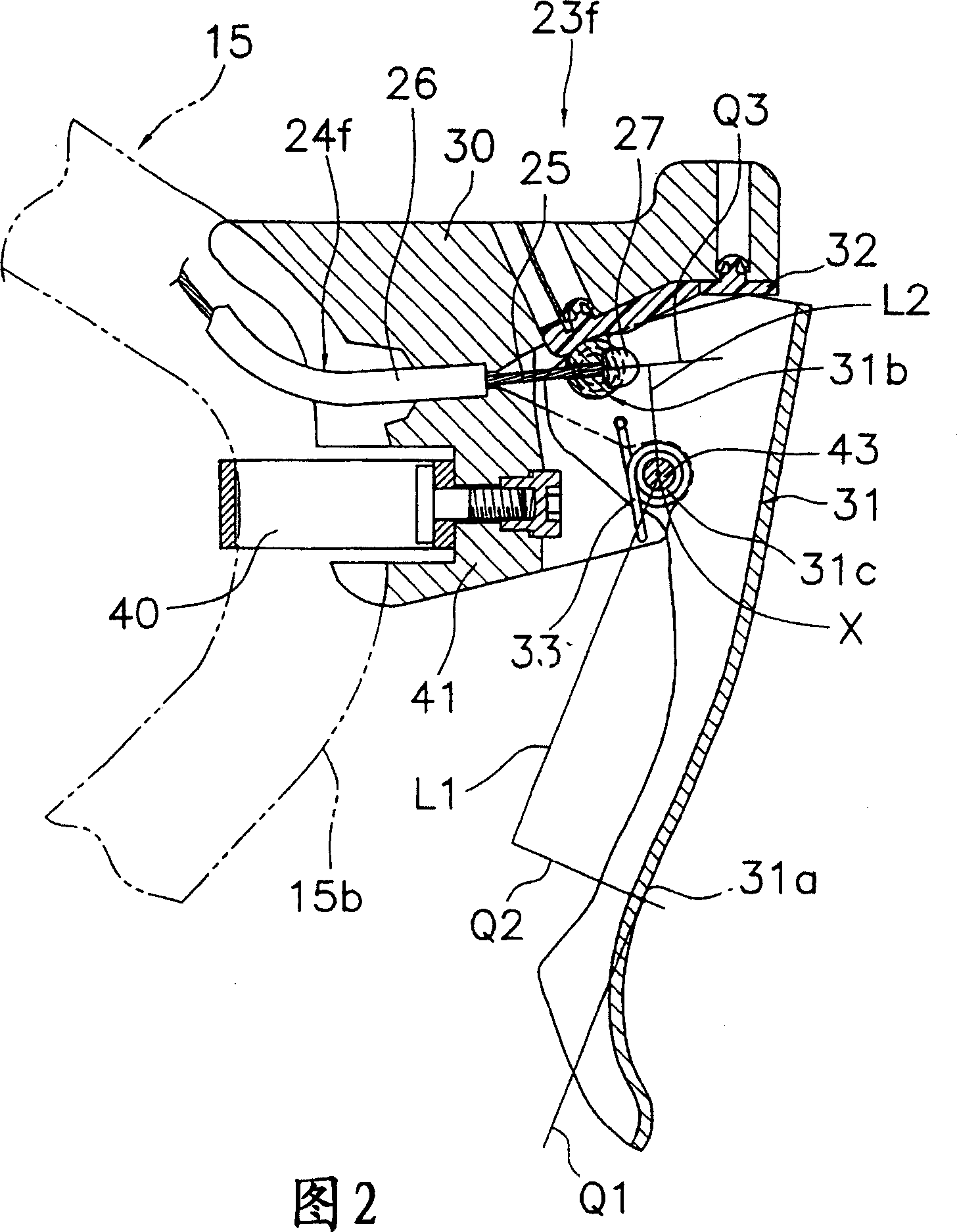
The invention provided a brake operation device for a bicycle including a brake operating mechanism capable of securing the stroke of a brake wire sufficiently even after adjustment of the brake release initial position. The brake operating mechanism 23f for the bicycle to be coupled with a brake device through the brake wire is equipped with a brake bracket 30, a lever 31, an adjusting member 32, and a torsion coil spring 33. The brake bracket can be attached to the handle bar, while the lever has a brake operation part 31a and a wire engaging part 31b to engage the brake wire 24f and is attached to the brake bracket swingably round the first axis X. The adjusting member 32 has an adjuster body part 55 mounted on the brake bracket, a first position adjustment part 56 provided in the adjuster body part and capable of adjusting the brake release initial position of the lever, and a second position adjustment part 57 provided in the adjuster body part and capable of adjusting the nipple initial position of a cable nipple when the lever is in the brake release initial position. The torsion coil spring energizes the lever to be biased to the brake release initial position.

Description

technical field [0001] The invention relates to a brake control device, in particular to a brake control device for a bicycle which can be installed on the handlebar of a bicycle and connected to the brake device through a brake wire with a locking wire joint fixed at the front end. Background technique [0002] A bicycle has a brake lever (an example of a brake operating device) mounted on the handlebar. The brake lever has a brake bracket installed on the handlebar, and a rod body that can swing freely on the brake bracket. The rod body is installed on the brake bracket, so that the control part can swing from the initial position of releasing the brake to the direction close to the handlebar. The lever body is arranged so that it does not depend on the shape of the handlebar, except that the opposite lever has its front end side away from both ends of the handlebar. The rod body is connected with the brake device through the brake wire, and usually has a tendency to mov...

Claims


Application Information

Patent Timeline
Patent Type & Authority Applications(China)
IPC IPC(8): B60T11/04B62K23/06B62L3/02
CPCY10T74/20438F16C1/22B62L3/02B62K23/06Y10T74/20287Y10T74/2028B60T11/046F16C2326/20
Inventor 名合大辅
Owner SHIMANO INC
Learn More