Supercharge Your Innovation With Domain-Expert AI Agents!

Connector for cards

A card connector and connector terminal technology, which is applied to the parts of the connection device, the device for connecting, connecting/disconnecting the connecting parts, etc. The miniaturization of the device and other issues can prevent buckling or deformation, improve contact reliability, and facilitate contact reliability.

Inactive Publication Date: 2005-05-04
ALPS ALPINE CO LTD
View PDF2 Cites 6 Cited by
  • Summary
  • Abstract
  • Description
  • Claims
  • Application Information

AI Technical Summary

Problems solved by technology

[0011] However, in the structure of the conventional card connector device, the contact (connector terminal) 52 held on the insulator (housing) 51 is inserted into the card 20 by forming the free end side of the contact 52a. direction from the inside to the front (card insertion slot direction), so there is a problem that, for some reason, the contact 52a is mounted to the lower side of the card housing portion, When the card 20 is inserted, the front end of the card 20 will collide with the front end of the contact 52a, which will cause the contact 52 to buckle or deform, resulting in poor contact.
[0012] In addition, in order to prevent the front end of the contact 52a from colliding with the front end of the card 20, and to bend it upward and protrude in advance, it is necessary to set the height of the insulator high so as not to touch the contact when the card 20 is inserted. The point 52a protrudes from the insulator (housing) 51, so there is another problem of increasing the size of the connector device
[0013] In addition, as long as the contact (connector terminal) 52 held on the insulator (housing) 51 is formed in such a manner that the free end side forming the contact 52a extends inward with respect to the insertion direction of the card 20, But in this case, just become the form that the holding part of contact 52 is oppositely positioned at the insertion port side of card accommodating part, so when card is inserted, when contact 52a of contact 52 contacts with card, as insulator The card insertion port side on the free end side of 51 will be bent toward the card receiving part side due to the elastic pressure of the contact 52, and the contact pressure with the card cannot be ensured.
[0014] In addition, in the structure of the conventional card connector device, the contact portion of the detection switch that detects the insertion state of the card is formed by a contact spring that rotates around the pivot point, and the contact spring is obtained by the same contact spring. The self-restoration of the point spring uses the elastic pressure and the contact pressure of the contact part. Therefore, after a long period of use, there will be problems such as the contact spring slack and falling down, the contact pressure drops, and the contact is unstable.
In addition, in order to increase the contact pressure, the contact spring must be enlarged, so the housing must be enlarged, so there is a problem that it is difficult to realize the miniaturization of the connector device.

Method used


Image

  • Connector for cards
  • Connector for cards
  • Connector for cards

Examples


Embodiment Construction

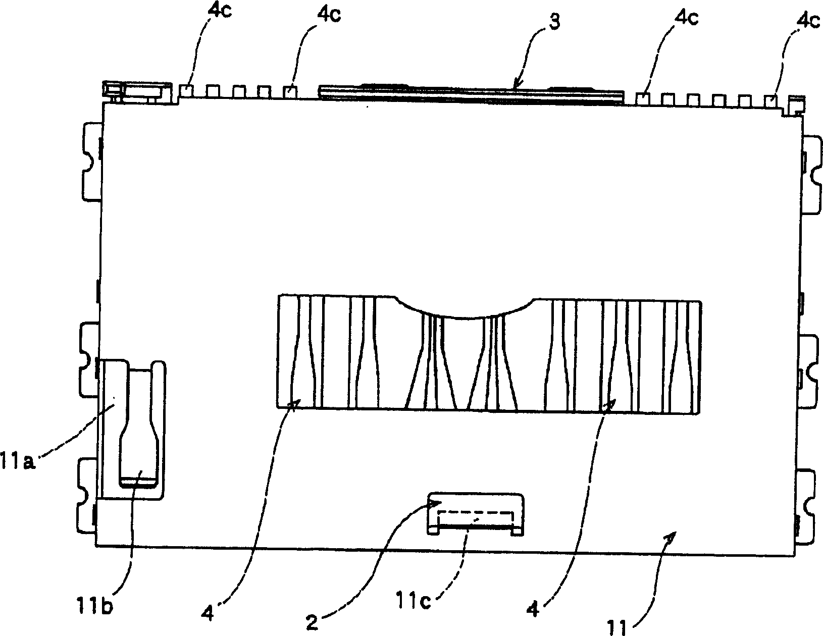
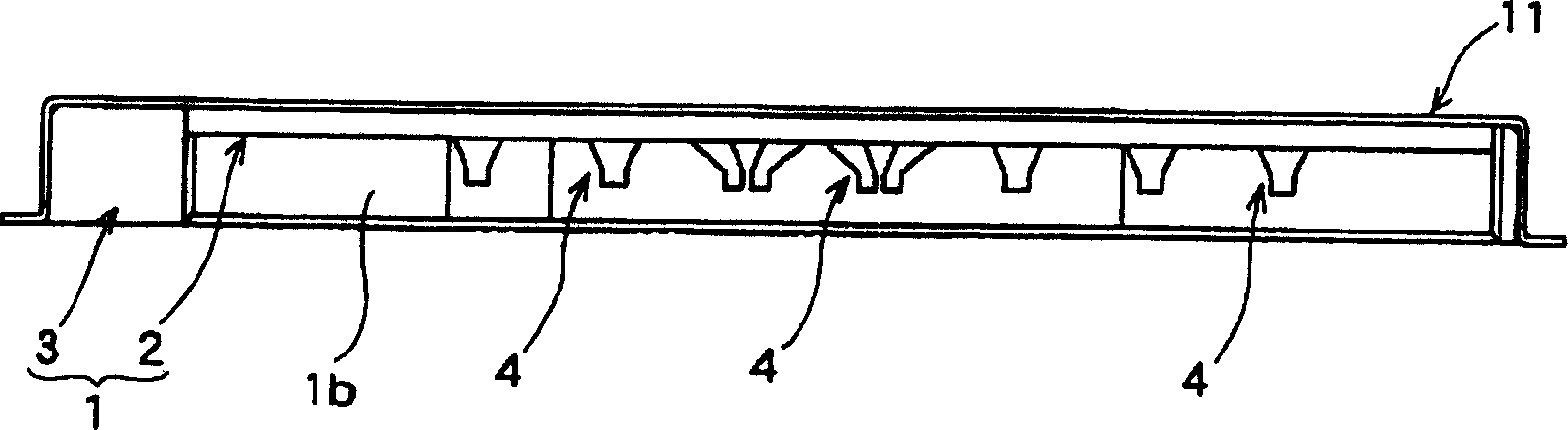
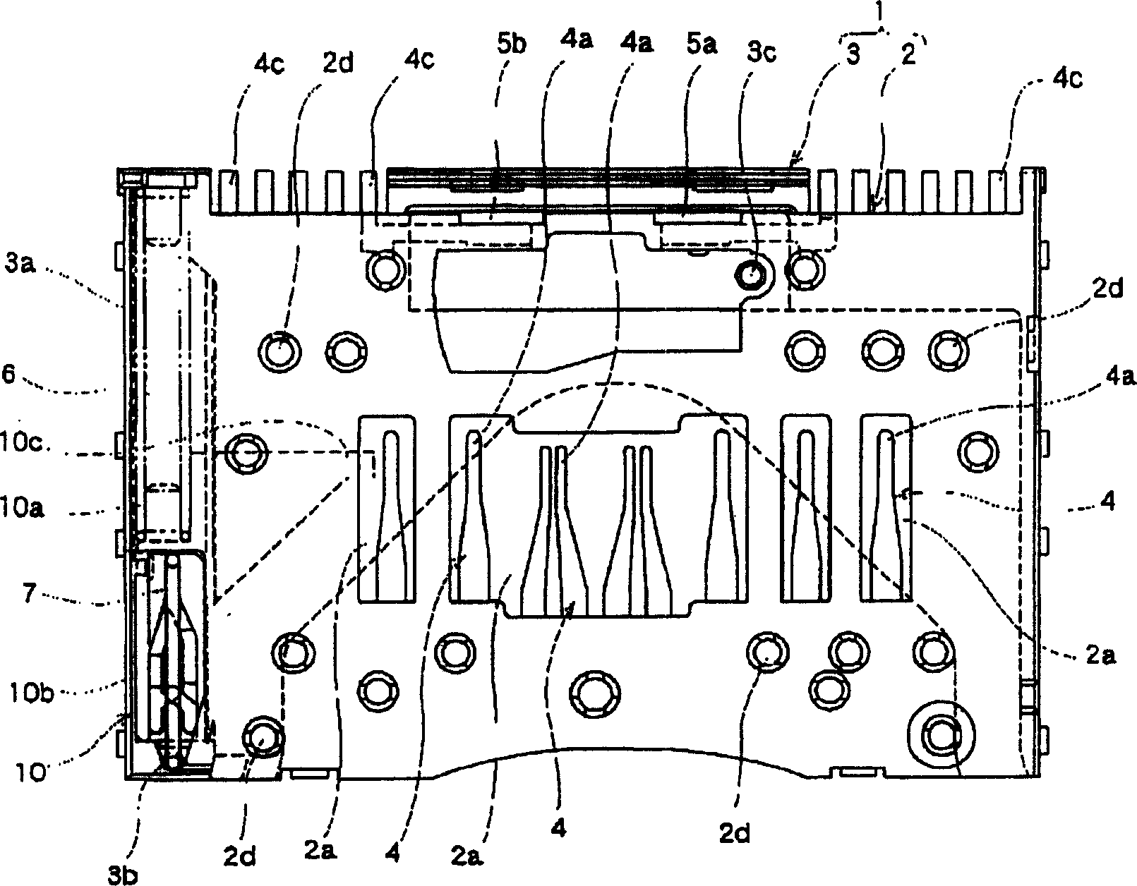
[0064] Hereinafter, the embodiment of the present invention is shown in Figure 1 ~ Figure 15 in. figure 1 Is the top view of the card connector device, figure 2 Is the front view of the card connector device, image 3 It is a plan view of the card connector device with the cover member removed, Figure 4 It is a cross-sectional view of the main part of the card connector device, Figure 5 It is a plan view of the card connector device at the card ejection position, Figure 6 It is a cross-sectional view of the main part of the card connector device at the card ejection position, Figure 7 It is a plan view of the card connector device in the middle of card insertion, Figure 8 It is a cross-sectional view of the main part of the card connector device in the middle of the card insertion, Picture 9 It is a top view of the card connector device at the card insertion position, Picture 10 It is a cross-sectional view of the main part of the card connector device at the card inserti...


PUM


Abstract

This invention provides a connector device for a card allowing the improvement of contact reliability of a contact part of a detection switch detecting insertion / installation of the card, and allowing miniaturization of the connector device. This connector device has: a lock member 7 holding a slide member 10 movable according to the insertion and discharge of a card in a card insertion / installation position; and a detection means detecting the insertion / installation of the card. The detection means has: first and second fixed contacts 5a, 5b provided in a housing 1; and a movable contact 9 connecting the first and second fixed contacts 5a, 5b. The movable contact 9 is formed of one twist coil spring having two end turn parts, the twist coil spring is formed with a first contact spring 9a abutting on the first fixed contact 5a and a second contact spring 9b abutting on the second fixed contact 5b, and the first contact spring 9a and the second contact spring 9b are respectively extended from the different end turn parts.

Description

Technical field [0001] The present invention relates to a structure of a connector device for a card used in a small memory card used in various portable information terminals such as mobile phones and PCs, digital cameras, digital AV machines, and other devices that use memory. Background technique [0002] As an additional storage device for electronic equipment such as a personal computer or a digital camera, a card connector device is generally used. As the storage medium of the card connector device, PC cards, memory cards, and the like are widely used. As this conventional card connector device, there is known a housing for inserting a card in a housing such as a housing, and a plurality of connector terminals (contacts) are arranged in parallel on the housing to make the connector A device that connects the contacts of the terminals to external contacts of a memory card or the like inserted in the accommodating portion to perform writing and reading of necessary informatio...

Claims


Application Information

Patent Timeline
IPC IPC(8): H01R12/70
CPCG06K7/0056G06K19/07732H01R12/70H01R13/635H01R13/639
Inventor 山田裕树川端隆志加贺谷浩之
Owner ALPS ALPINE CO LTD
Features
  • R&D
  • Intellectual Property
  • Life Sciences
  • Materials
  • Tech Scout
  • Unparalleled Data Quality
  • Higher Quality Content
  • 60% Fewer Hallucinations
Learn More