
Locust catcher by photoelectric induction

A locust and photoelectric technology, which is applied in the field of locust trapping machines, can solve the problems of microwave electromagnetic pollution and environmental safety, and achieve the effects of improving the trapping efficiency, good trapping effect and strong adaptability of locusts.

Inactive Publication Date: 2005-05-11
CHINA AGRI UNIV
View PDF3 Cites 39 Cited by
  • Summary
  • Abstract
  • Description
  • Claims
  • Application Information

AI Technical Summary

Problems solved by technology

This method realizes the non-toxic extermination of locusts with the help of microwave electromagnetic energy, but the electromagnetic pollution and environmental safety issues of microwave are worth noting.

Method used


Image

  • Locust catcher by photoelectric induction
  • Locust catcher by photoelectric induction
  • Locust catcher by photoelectric induction

Examples


Embodiment Construction

[0018] The self-powered photoelectric induction locust trapping machine will be further described below in conjunction with the accompanying drawings and embodiments.

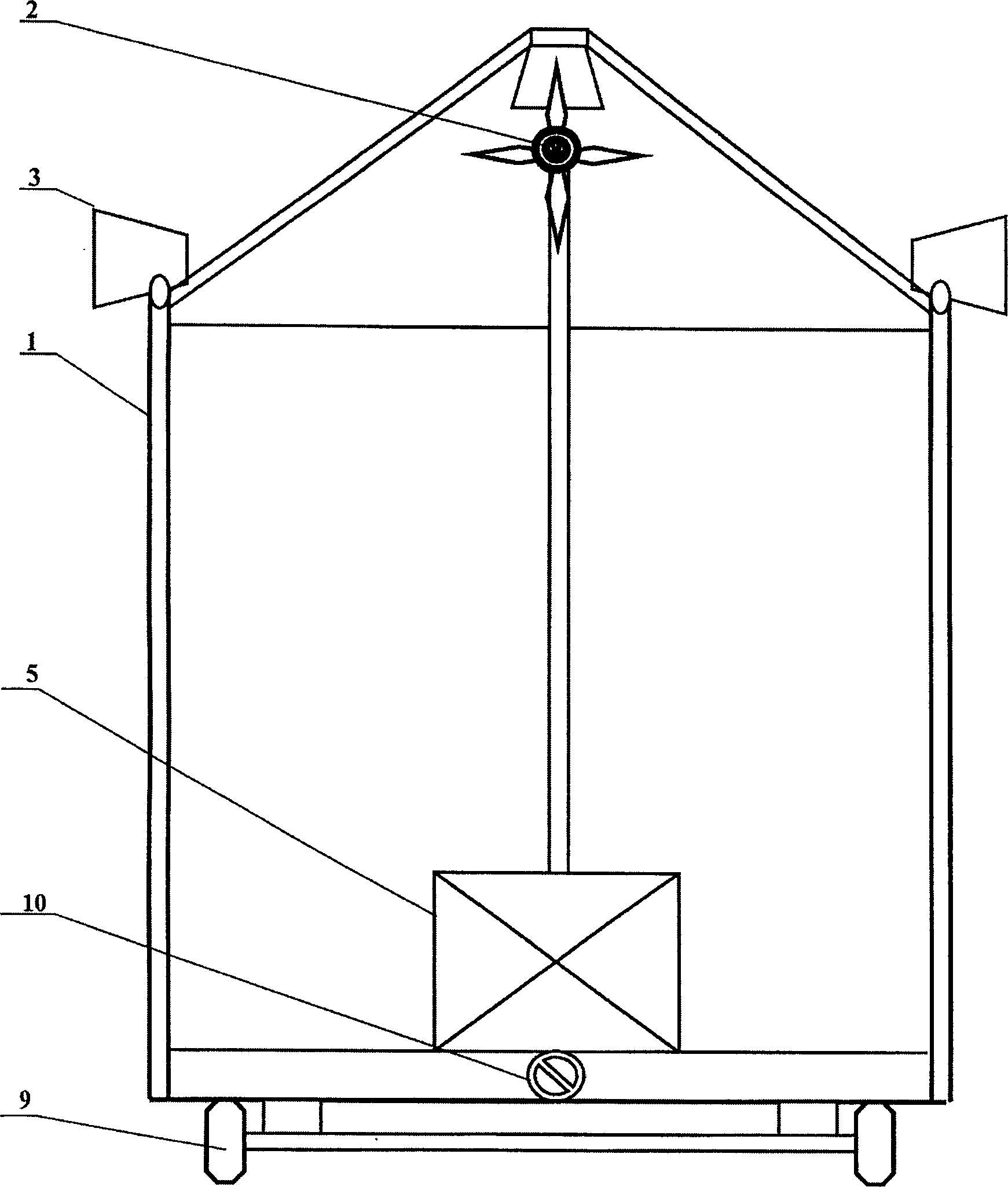
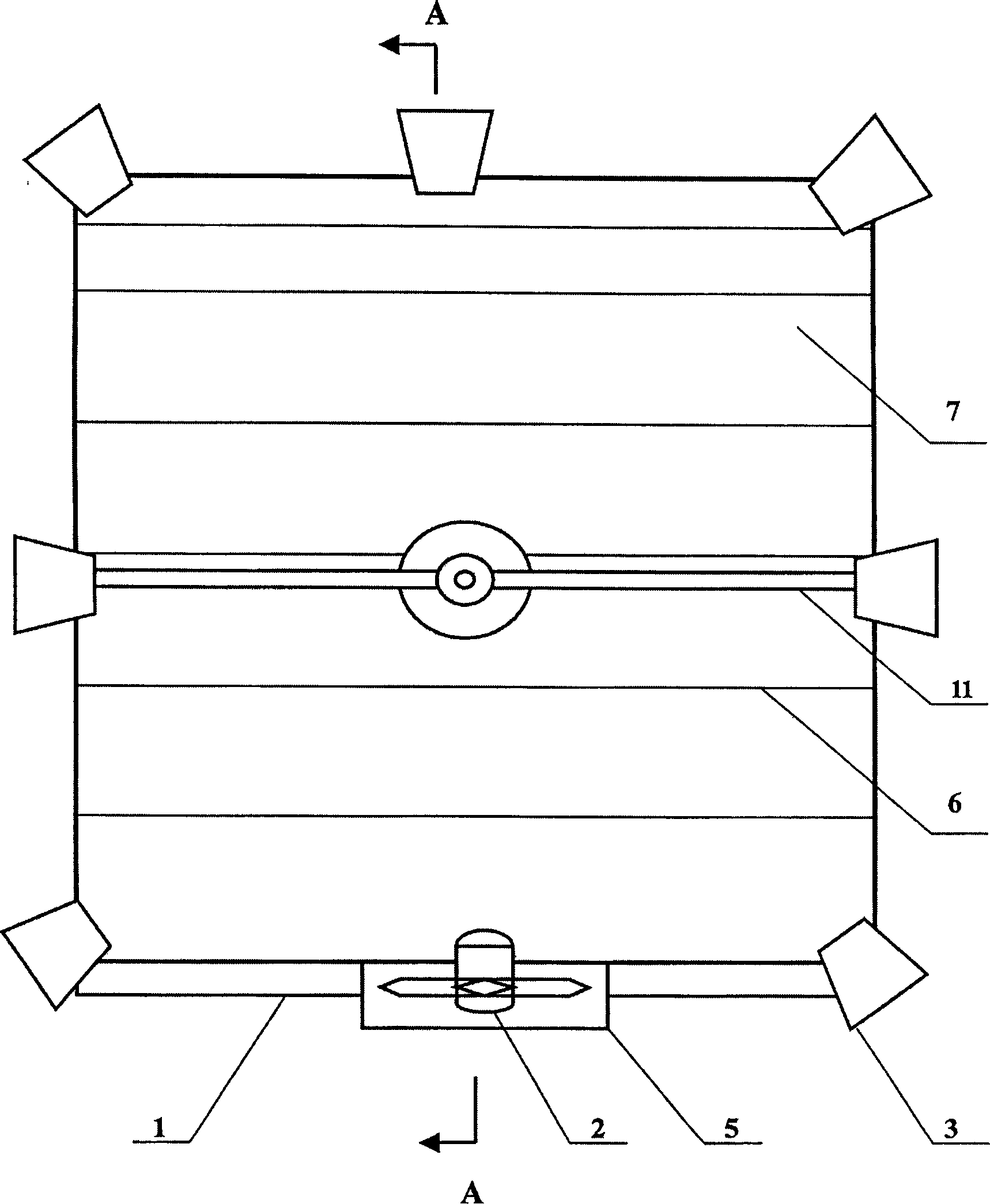
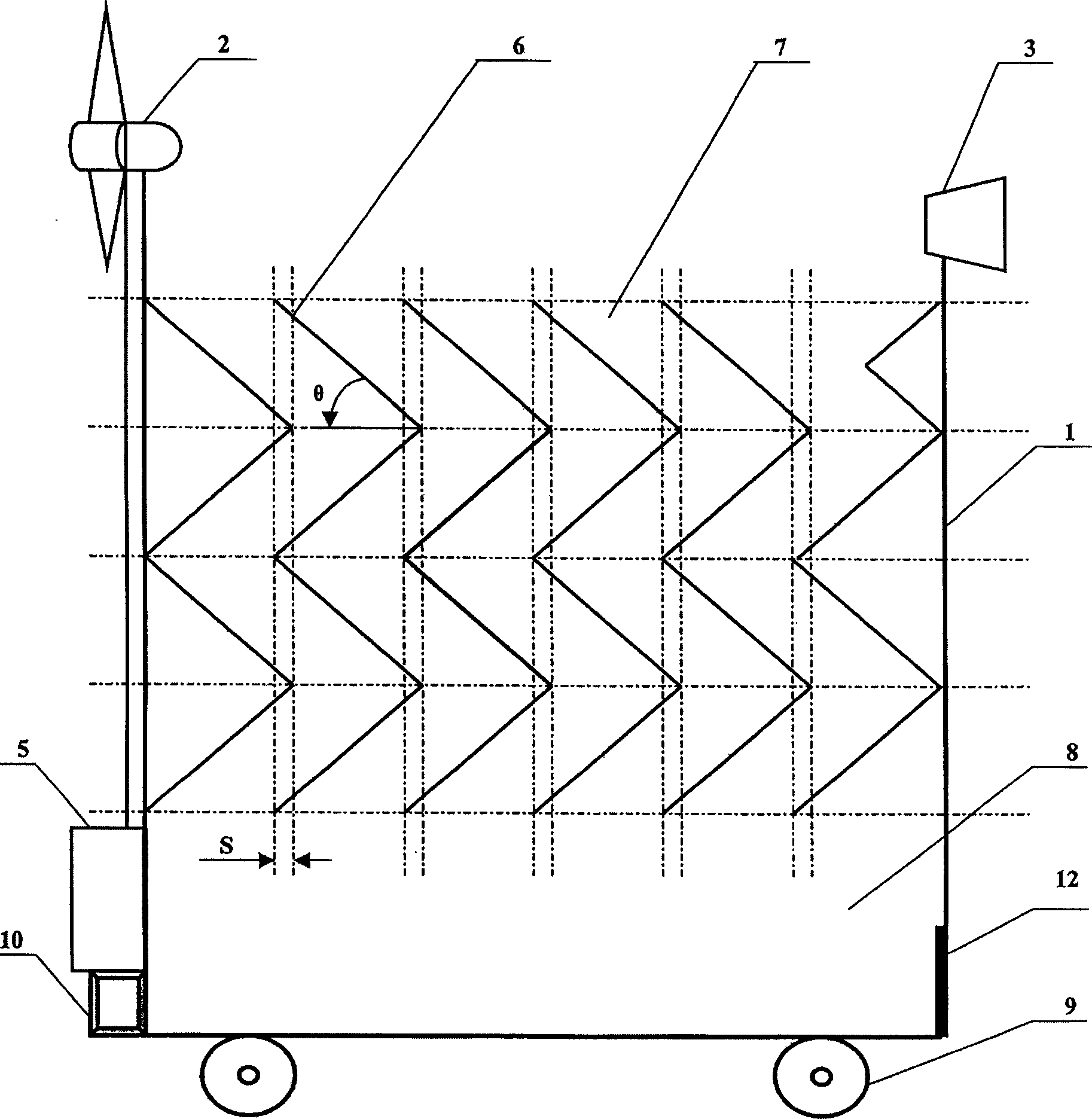
[0019] Such as figure 1 , figure 2 As shown, 1 is the catcher box, 2 is a wind generator or / and a photovoltaic cell as a self-powered power supply, 3 is a light source, 5 is a control device, and 6 is a group of vertical pleated locusts arranged in the catcher box Skateboard, 7 is the pleat-shaped drop gap formed between two pleat-shaped locust slide plates 6, and 8 is a locust collection room, which is located under the pleat-shaped drop gap 7, and 9 is a mobile roller installed at the bottom of the catcher casing 1 10 is the traction hook located at the front of the catching machine casing 1 for dragging and walking when moving in different places, and 11 is a crossbeam located on the catching machine casing 1.

[0020] The catcher box 1 plays the role of supporting the entire capture mechanism. In this em...


PUM


Abstract

A photoelectric attractive capturer for locusts is composed of a case body containing a group of vertical corrugated plates with gap between adjacent ones for dropping the locusts in it, a light source, and a locust collecting chamber under said gaps.

Description

technical field [0001] The invention relates to a locust catcher which utilizes photoelectric effect to induce locusts, and belongs to the field of plant protection machinery. Background technique [0002] In my country, locust disasters occur in tens of millions of acres of farmland and grassland every year, which has a destructive impact on agricultural crops and grassland ecology. Prevention and control of locust disasters requires a lot of manpower, material resources and funds. The locust control methods based on chemical insecticides have caused pollution to the natural ecological environment and harm to people's survival and life while killing the locusts with toxicity; From the perspective of resource utilization, good locust biological protein resources are killed by toxicity, which hinders the effective utilization of this natural germplasm. Therefore, the large-scale, non-toxic and harmless method of killing and killing locust colonies has become a locust control...

Claims


Application Information

Patent Timeline
IPC IPC(8): A01M1/04
Inventor 周强徐瑞清杨柳
Owner CHINA AGRI UNIV
Learn More