Heating method of ladle

A heating method and ladle technology, applied in chemical instruments and methods, metal processing equipment, metallurgical equipment, etc., can solve problems such as damage, troublesome work, and time-consuming

Inactive Publication Date: 2005-05-11
JFE STEEL CORP
View PDF1 Cites 3 Cited by
  • Summary
  • Abstract
  • Description
  • Claims
  • Application Information

AI Technical Summary

Problems solved by technology

[0016] However, the above-mentioned conventional ladle heating method has the following problems: the work of moving the ladle cover with the burner with a crane, etc., and opening and closing the upper opening of the ladle is troublesome and time-consuming. The edge of the upper opening is damaged by the impact of the lid on the upper opening of the ladle

Method used


Image

  • Heating method of ladle
  • Heating method of ladle
  • Heating method of ladle

Examples


Embodiment Construction

[0044] 1) Invention No. 1 and Invention No. 5

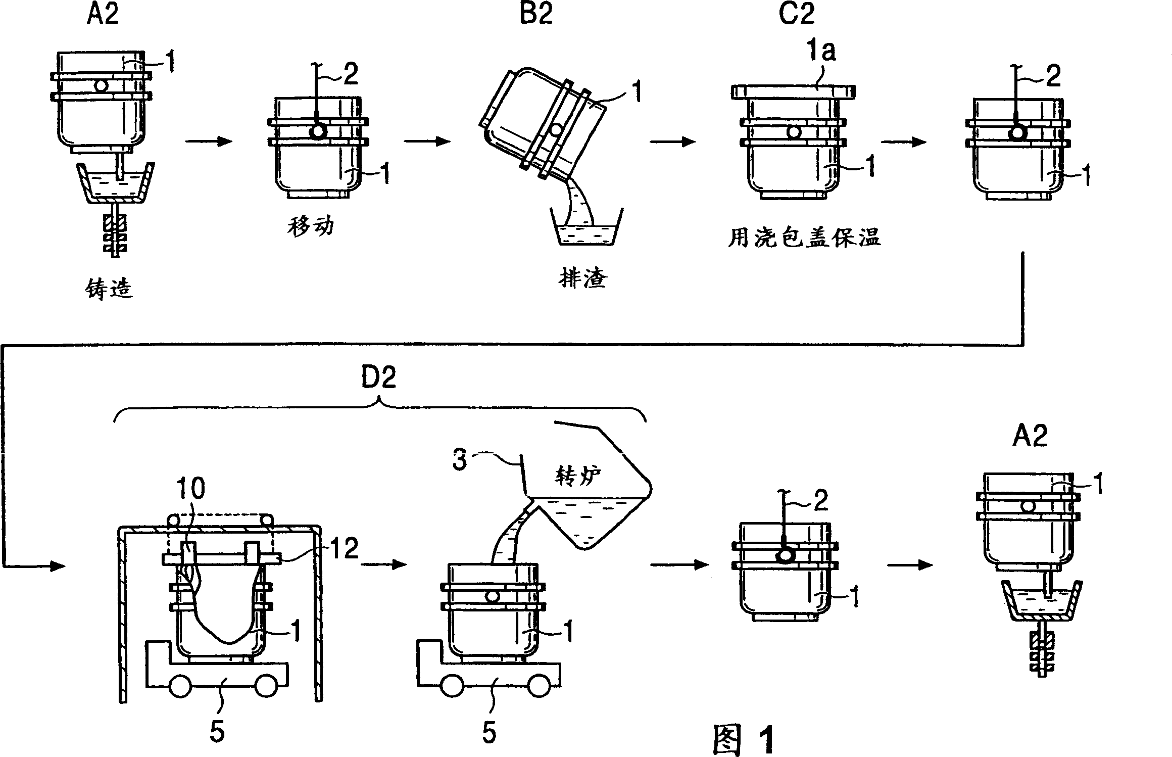
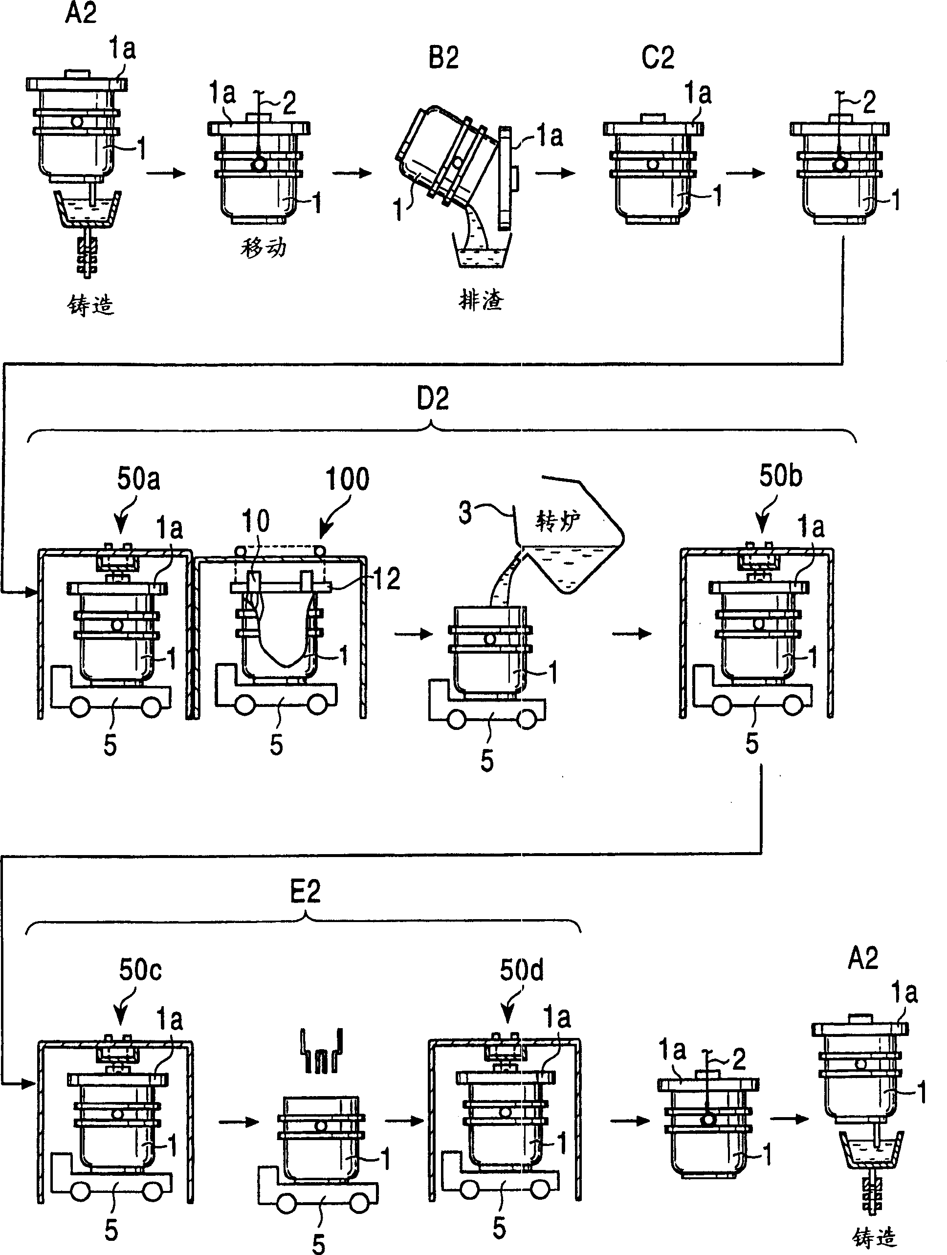
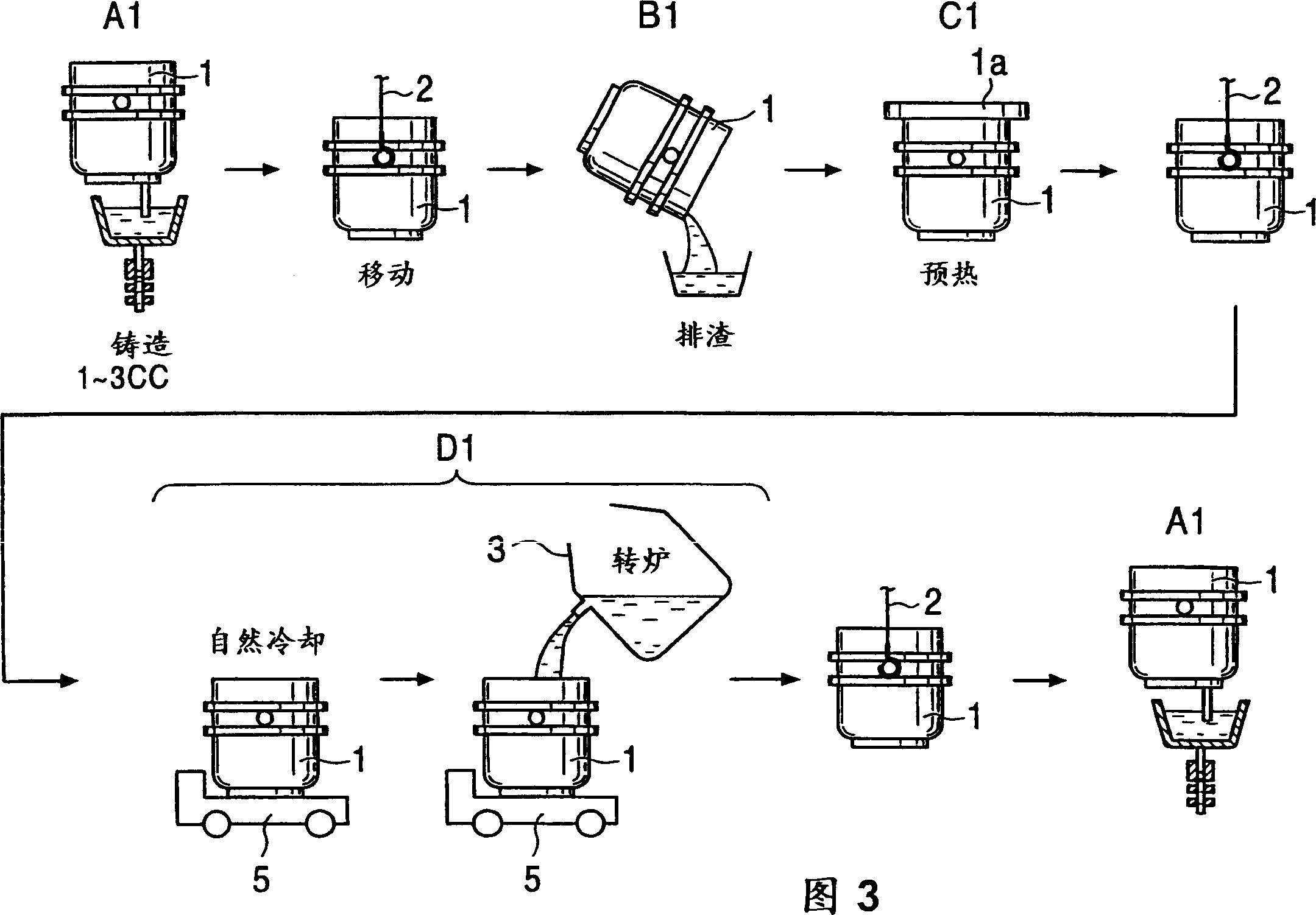
[0045] An example of an embodiment of the present invention will be described below with reference to the drawings. Fig. 1 is an explanatory diagram for explaining an example of an embodiment of the present invention, that is, a method of heating a ladle, Figure 4 It is an explanatory diagram for explaining the method of rapidly heating the ladle on the molten steel trolley when it is on standby in the tapping area with a regenerative burner, Figure 5 yes Figure 4 top view of Image 6 It is a schematic diagram for explaining the operation of the regenerative burner.

[0046] (1) Rapid heating method

[0047] Referring to Fig. 1, the ladle 1 used in converter operation is moved to the slag discharge area B2 by a crane 2 after continuous casting, and the ladle 1 is tilted in the slag discharge area B2 to discharge the steel slag remaining inside. Then, move to the maintenance inspection area (not shown), and after cleaning ...


PUM


Abstract

A method of heating the ladle before receiving molten steel. After continuous casting and slag removal, the ladle is placed on the molten steel trolley, and then transported by the molten steel trolley to the tapping area of ​​the converter, and then placed on the molten steel trolley 1. Stand by in the tapping area for a specified time to form a standby state. After the standby, the molten steel flowing out from the converter is immediately received, and the ladle is heated before receiving the molten steel. In the tapping area of ​​the converter, it is in a standby state. The ladle is heated rapidly within a specified time. This rapid heating is carried out by means of a regenerative burner installed on the ladle cover covering the upper opening of the ladle.

Description

technical field [0001] The invention relates to a method of heating a ladle used in the operation of a converter for conveying molten steel of the converter. Background technique [0002] 1) Referring to Figure 3, the ladle 1 used in converter operation is moved to the slag discharge area B1 by a crane 2 after continuous casting, and the ladle 1 is tilted in the slag discharge area B1, so that the slag remaining inside discharge. Then, it moves to a maintenance inspection area (not shown), and after the slide nozzle is cleaned or replaced in this maintenance inspection area, it moves to a preheating area C1. In this preheating zone C1, the ladle 1 is heated by the burner 4 etc. in order to dry the ladle 1 and to compensate the temperature drop of the molten steel received from the converter 3. [0003] Next, the ladle 1 is placed on the molten steel trolley 5 by a crane 2 or the like, and transported to the tapping area D1 of the converter 3 in this ...

Claims


Application Information

Patent Timeline
Patent Type & Authority Applications(China)
IPC IPC(8): B22D11/10B22D11/00B22D41/015B22D41/12
CPCB22D41/015B22D41/12Y10S266/901B22D11/00
Inventor 原一晃安达一成野村宽须田守高桥大辅后藤信孝高桥清志永井亮次
Owner JFE STEEL CORP
Why Eureka
Try Eureka