Automatic descaling delaying valve

A technology of automatic descaling and time-delay valves, which is applied in the direction of valve devices, functional valve types, engine components, etc., can solve the problems of increasing user cost and maintenance cost, increasing manufacturing difficulty and cost, and limiting the service life of diaphragms, etc. problem, to achieve the effect of stable and reliable self-control delay, cost reduction, and labor-saving operation

Inactive Publication Date: 2005-05-11
邝栋材
View PDF3 Cites 9 Cited by
  • Summary
  • Abstract
  • Description
  • Claims
  • Application Information

AI Technical Summary

Problems solved by technology

However, this structure has high requirements on the comprehensive quality of the diaphragm, button cover and water supply environment, and the addition of a limit retaining ring will undoubtedly increase the manufacturing difficulty and cost, and the service life of the diaphragm is also limited, thereby increasing reduce the user's use cost and maintenance cost

Method used


Image

  • Automatic descaling delaying valve

Examples


Embodiment Construction

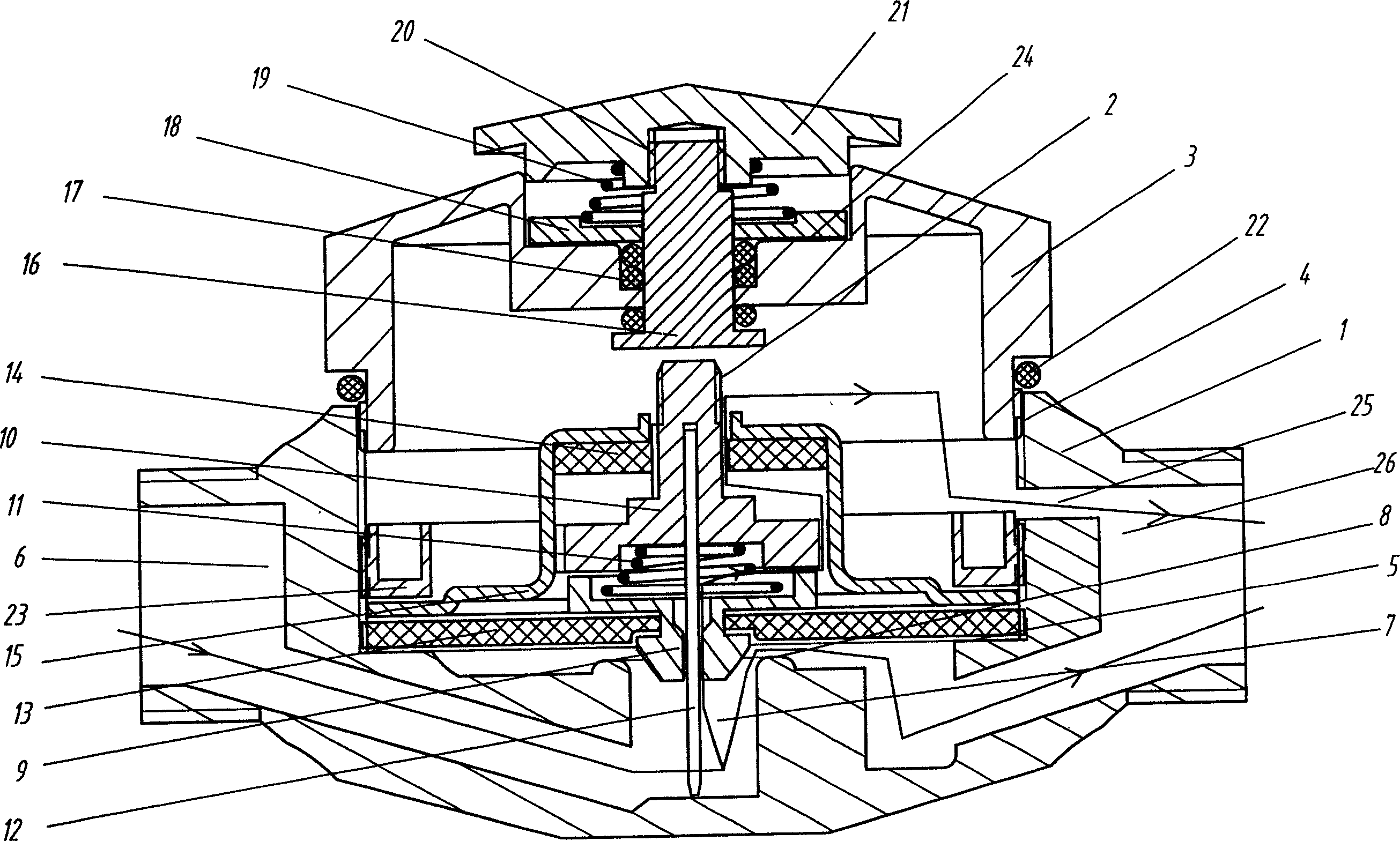
[0012] It can be seen from the drawings that the automatic descaling delay valve includes a valve body 1, a valve core assembly 2 fixed in the valve body and a valve cover 3 connected to the valve body 1, wherein the valve body is provided with an open inner cavity, and the inner cavity The wall is provided with threads 4 for connecting the "convex" shaped gland 15, the fastening ring 23 and the valve cover 3. A sealing platform 5 is provided at the bottom of the inner chamber, and a water inlet hole 7 in the center of the inner chamber communicated with the water inlet connection interface 6 is arranged in the center. The water inlet hole 7 is provided with a sealing boss 8 along the edge, so as to make the structure of the valve body 1 more compact and the shape more compact. Aesthetically pleasing, the shape of the valve body 1 is in the shape of a "turtle body" or "round cake", and the inlet and outlet water connection interfaces 6, 26 are arranged on the center line of the...


PUM


Abstract

A delay valve able to automatically remove the water scale is composed of valve body, valve core module and valve cover. It features that its flexible damping valve core consisting of two half-open dampers and spring is combined with the steel needle and big and small sealing membranes to form a multi-sealing scheme, realizing the float, flexible and delayed water discharge, automatically controlled sealing, and automatically removing water scale.

Description

technical field [0001] The invention relates to a valve, in particular to an automatic descaling delay valve. Background technique [0002] There are many types of valves that combine damping and valve needles to form a damping spool system to reduce the occurrence of clogging, such as elimination devices for reducing vibration, injection valves for fuel delivery, and electromagnetic hydraulic valves for controlling hydraulic systems. , Delay valve for flushing, etc. Especially for the delay valve for direct flushing, there is also a damping valve needle structure to reduce the blockage of the damping hole by scale and cause poor water supply. In this type of structure, the traditional long pull rod is mostly used as the starting rod to achieve the purpose of labor-saving operation and easy maintenance. But this type of structure is not suitable for horizontal structure and can only be used as vertical structure, so the scope of use is limited, such as the tie rod structur...

Claims


Application Information

Patent Timeline
Patent Type & Authority Applications(China)
IPC IPC(8): F16K21/04
Inventor 邝栋材
Owner 邝栋材
Why Eureka
Try Eureka