Voltage controlled oscillator for reducing gain surge

A voltage-controlled oscillator and voltage-controlled technology, applied in power oscillators, electrical components, etc., can solve problems such as no voltage-controlled oscillators

Active Publication Date: 2005-05-11
PEKING UNIV +1
View PDF0 Cites 7 Cited by
  • Summary
  • Abstract
  • Description
  • Claims
  • Application Information

AI Technical Summary

Problems solved by technology

And an effective solution is to reduce the K when designing the VCO VCO fluc

Method used


Image

  • Voltage controlled oscillator for reducing gain surge
  • Voltage controlled oscillator for reducing gain surge
  • Voltage controlled oscillator for reducing gain surge

Examples


Embodiment Construction

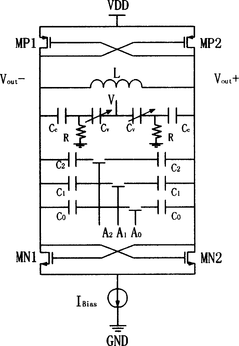
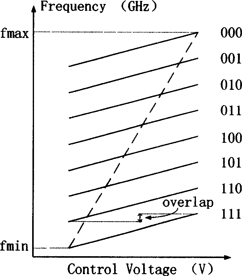
[0025] Such as Figure 5 As shown, the present invention is in figure 2 It is improved on the basis of medium voltage controlled oscillator circuit. and figure 2 In contrast, the present invention first changes the control voltage V of the voltage controlled oscillator 1 After a voltage conversion circuit, the actual control voltage V 2 , then V 2 It is sent to the control terminal of the varactor in the voltage-controlled oscillator. The function of the voltage conversion circuit is to convert a voltage control signal varying within a certain voltage range to a voltage control signal varying within another voltage range. This process is as Figure 6 shown, for example, when the voltage V 1 from V x1 to V x2 changes when V 2 Then from V y1 to V y2 Variety. Figure 7 A specific implementation form of the voltage conversion circuit is given, which consists of a digital control bit A 2 A 1 A 0 synchronous control. by right Figure 7 Middle R 0 ~R 3 The value...


PUM


Abstract

The invention consists of LC resonance loop used in providing negative conductance active device. The voltage control end of the voltage controlled oscillator is connected with the voltage transform circuit. The invention can vary the voltage of voltage controlled oscillator to vary the range of frequency modulation and control the gain of voltage controlled oscillator.

Description

technical field [0001] The invention relates to a voltage-controlled oscillator, in particular to a voltage-controlled oscillator with small gain fluctuation. Background technique [0002] In the past ten years, personal wireless communication systems such as pagers, cordless phones, analog and digital cellular phones, as well as digital TV and broadcasting have developed rapidly, and wireless communication has become the most important industry after the PC industry. Due to the characteristics of small size, low power consumption and low cost of integrated circuits, the vigorous development of wireless communication technology has contributed to the rapid development of radio frequency integrated circuits. At present, radio frequency integrated circuits have become one of the important research fields of microelectronics. Designing and researching high-performance key circuit modules has become a vital driving force for the advancement of radio frequency integrated circuit...

Claims


Application Information

Patent Timeline
IPC IPC(8): H03B5/12
Inventor 石浩张国艳廖怀林黄如张兴王阳元
Owner PEKING UNIV
Why Eureka
Try Eureka