

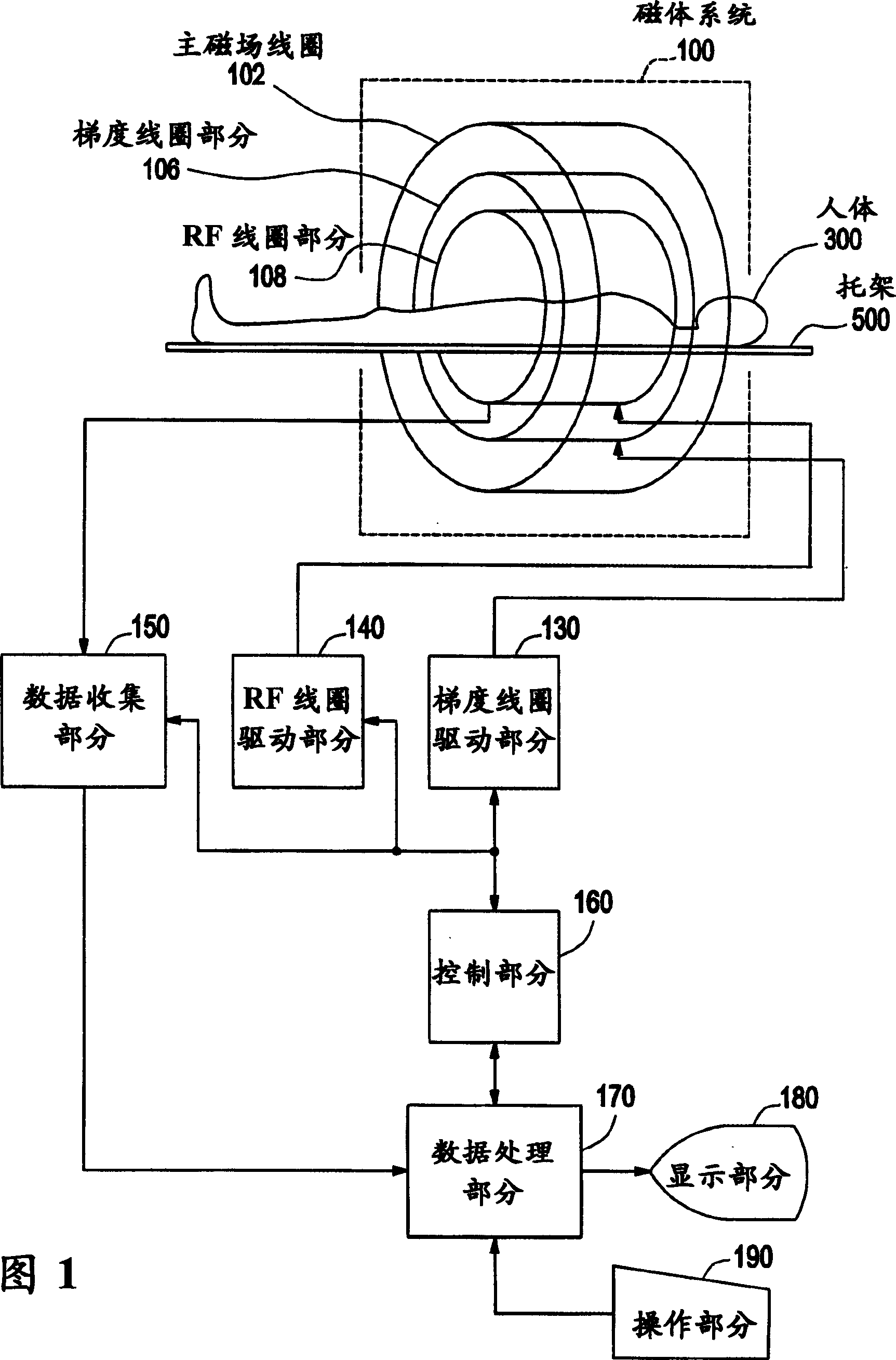
MRI method and MRI apparatus
A technology of magnetic resonance imaging and magnetic resonance image, which is applied in the direction of magnetic resonance measurement, measurement using nuclear magnetic resonance imaging system, and measurement equipment, can solve the problems of large influence, unavoidable influence of calculation error, and inaccurate calculation, etc., to achieve Effect of reducing signal strength, easy to calculate contrast
- Summary
- Abstract
- Description
- Claims
- Application Information
AI Technical Summary
Problems solved by technology
Method used
Image

Examples
no. 1 example
[0132] [First embodiment, T1 weighting]
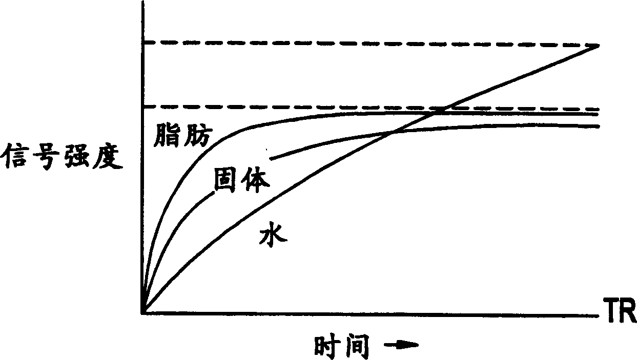
[0133] Next, the T1 weighting as the first embodiment of the weighting process of the present invention will be explained.
[0134] For example, the following equation 1 gives the signal strength S of the MR signal in the SE technique or the FSE technique.
[0135] [Equation 1]
[0136] S=ρ{1-exp(-TR / T1)}exp(-TE / T2)...(1)
[0137] Where ρ is the concentration of hydrogen.
[0138] Thus, the following signal strengths S1 and S2 are applied to the MR signal (echo signal), which is used to assume that the echo time TE is the same but the repetition time TR is different (ie, the first and second repetition times TR1 and TR2, where TR1<TR2) the image generation process.
[0139] [Equation 2]
[0140] S1=ρ{1-exp(TR1 / T1)}exp(-TE / T2)
[0141] S2=ρ{1-exp(TR2 / T1)}exp(-TE / T2)...(2)
[0142]The following equation 3 gives the difference (S1-S2) between the signal intensities S1 and S2 of the two MR signals in the SE or FSE technique. The difference is ...
no. 2 example
[0169] [Second embodiment: T2 weighting]
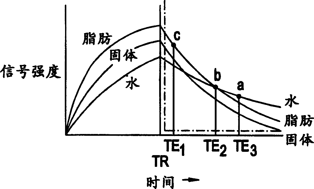
[0170] Next, the T2 weighting as the second embodiment of the weighting process of the present invention will be explained.
[0171] The specific T2 value can be weighted in a method similar to the first embodiment.
[0172] In the case of performing two PSDs with the same repetition time TR and different echo times TE (that is, different first and second echo times TE1 and TE2, where TE1<TE2), the different echo times TE1 and TE2 are the same as The signal intensities Sa and Sb correspond to each other, and are expressed by Equation 5 below.
[0173] [Equation 5]
[0174] Sa=ρ{1-exp(-TR / T1)}exp(-TE1 / T2)
[0175] S2=ρ{1-exp(-TR / T1)}exp(-TE2 / T2)...(5)
[0176] The following equation 6 gives the difference (Sa-Sb) between the signal intensities Sa and Sb of the two MR signals. Taking (Sa-Sb) as an example (thus TE1
[0177] [Equation 6]
[0178] Sa-Sb=ρ(1-exp(-TR / T1))
[0179] x(exp(-TE1 / T2)-exp(-TE2 / T2))...(...
no. 3 example
[0184] [Third Embodiment: Normal Weighting]
[0185] The third embodiment of the weighting process according to the present invention preferably uses two types of contrasts to generate an image, and the weighting process only weights tissues with specific T1 and T2 values.
[0186] For example, the third embodiment uses PSD for SE technology or FSE technology.
[0187] In the third embodiment, images with different TR and TE are measured multiple times to generate an image with a specific contrast. These images are then combined to weight only tissues with specific T1 and T2 values.
[0188] For example, the contrast of SE technology is usually expressed by the following equation.
[0189] [Equation 8]
[0190] Σ n ρ n ( 1 - exp ( - TR m ...
PUM
 Abstract
Description
Claims
Application Information