Method of spinning yarn in spindleless spinning machine including fiber collecting surface as well as apparatus for making the same

A spinning machine, yarn technology, applied in the field of devices implementing the method, capable of solving the problems of speed ratio difference, yarn volume loss, reduction, etc.

Inactive Publication Date: 2005-06-01
利特英格纺织机械制造股份公司
View PDF0 Cites 1 Cited by
  • Summary
  • Abstract
  • Description
  • Claims
  • Application Information

AI Technical Summary

Problems solved by technology

And each deceleration inevitably results in a loss of the amount of yarn produced
In addition, in terms of the quality of the yarn produced, there is also a reduction
Because of the change in speed, it can cause the difference in the speed ratio between the machines

Method used


Image

  • Method of spinning yarn in spindleless spinning machine including fiber collecting surface as well as apparatus for making the same
  • Method of spinning yarn in spindleless spinning machine including fiber collecting surface as well as apparatus for making the same
  • Method of spinning yarn in spindleless spinning machine including fiber collecting surface as well as apparatus for making the same

Examples


Embodiment Construction

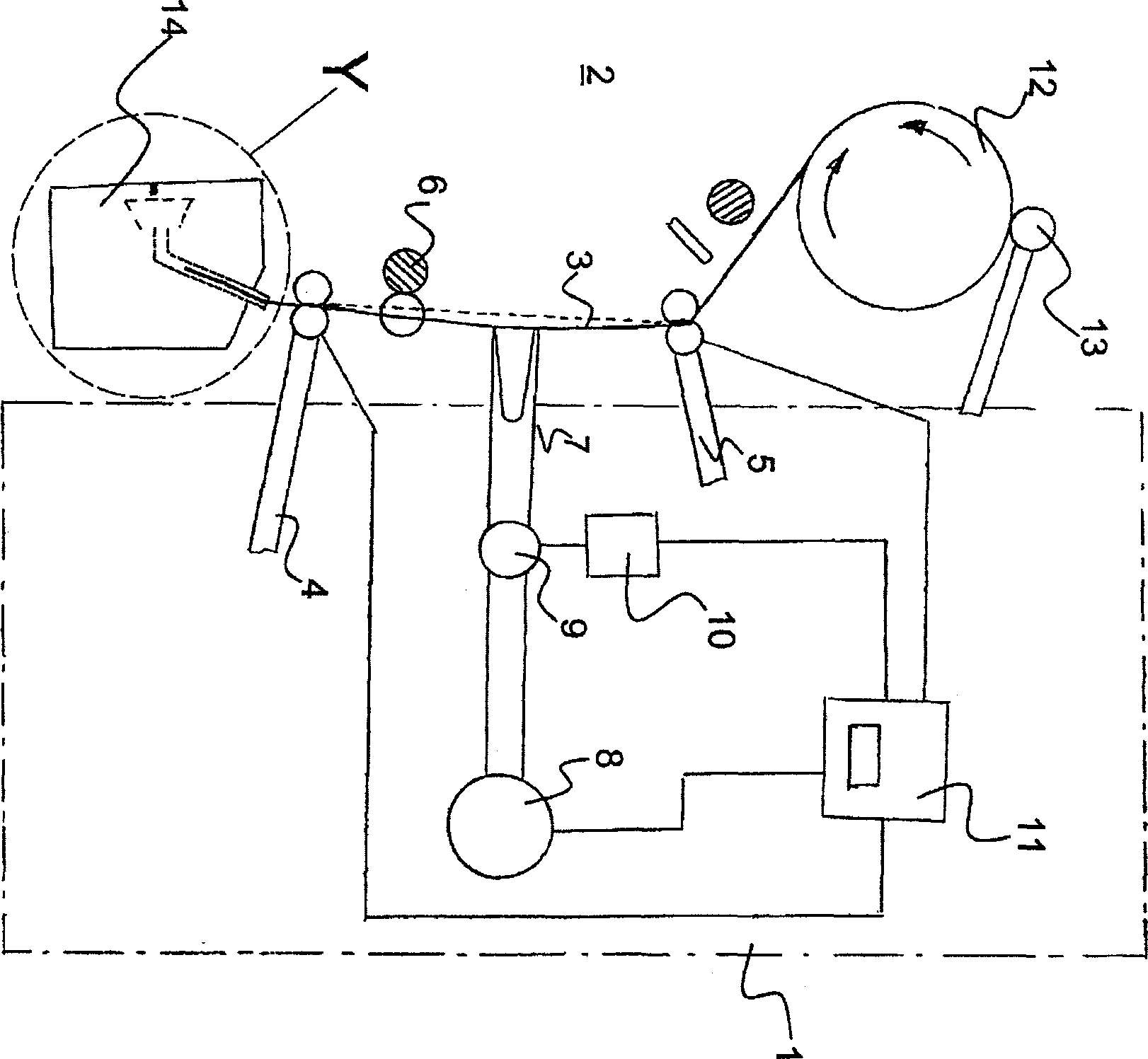
[0024] figure 1 A maintenance device 1 is schematically shown in . The maintenance device 1 is located in front of an open-ended spinning machine 2 which is only partially shown. The maintenance device 1 has a first pair of auxiliary rollers 4 and a second pair of auxiliary rollers 5 for gripping the yarn 3 . Between the first and second auxiliary roll pair 4 , 5 is a main roll pair 6 , which belongs to the open-end spinning frame 2 . A yarn storage device 7 is also arranged between the two auxiliary roller pairs 4,5. The shown yarn storage device 7 consists of a vacuum source 8 , a valve 9 and a servo drive 10 . Both the vacuum source 8 and the servo drive 10 are connected to a control device 11 and are regulated by it. Also connected to the control device 11 are the above-mentioned two pairs of auxiliary rollers 4 and 5 . In the shown state, the bobbin 12 on which the yarn 3 is wound on the open-end spinning machine 2 is driven by an auxiliary drive mechanism 13 of the ...


PUM


Abstract

The invention relates to a method for starting the spinning of a yarn (3) on an open-ended spinning frame (2) having a fiber collecting surface, wherein one of the yarns (3) to be spun After forming a surplus of yarn, the end (15) is fed into and held there in the action zone of a suction air flow which flows into the open-port spinning frame (2) and subsequently, The yarn (3) is loosened and conveyed to the fiber collection surface by unwinding the surplus yarn. From there, the yarn (3) is combined with the fibers provided by the fiber gathering surface and drawn again. The method is characterized in that the surplus yarn section is formed by a constant first yarn length, which is drawn backwards in a yarn accumulator (7). This back pull is released at a first point in time. At a second point in time the yarn (3) is loosened so that the yarn (3) is fed into the open-end spinning frame (2), and at a third point in time the predetermined first yarn The thread length delivery is adjusted to a necessary, variable second yarn length, wherein the three time points are coordinated with each other, so that the delivery process to the second yarn length adjustment starts from the third time point, It ends at the latest when the yarn reserve in the yarn storage device is exhausted.

Description

technical field [0001] The present invention relates to a method for the initiation of spinning of a yarn used in an open end worsted spinning machine having a fiber collecting surface, and to a device for carrying out the method. [0002] In this method, an end of the spun yarn is conveyed into the active area of ​​the suction air flow and held there by means of two pairs of auxiliary rollers forming a surplus section of the yarn, which The air flow flows into the open port worsted spinning machine. Next, the yarn is loosened and conveyed by the loosening of the surplus yarn to the fiber collecting surface, from where the yarn is combined with the fibers conveyed by the fiber collecting surface and then drawn. Background technique [0003] On modern open end worsted spinning machines it is often necessary to reconnect the yarn or start spinning for various reasons. For example, when the yarn breaks, or when respinning with an empty spool. As a result, machinery operators...

Claims


Application Information

Patent Timeline
Patent Type & Authority Applications(China)
IPC IPC(8): D01H4/48
Inventor F·拜尔
Owner 利特英格纺织机械制造股份公司
Why Eureka
Try Eureka