Cooling device of engine

A cooling device and engine technology, which is applied to the cooling of engines, engine components, machines/engines, etc., can solve problems such as large size, complex structure, and reduced temperature sensitivity of the thermostat, and achieve simplified structure, compact structure, and reduced assembly. and the effect of the disassembly process

Active Publication Date: 2005-06-01
MITSUBISHI MOTORS CORP +1
View PDF1 Cites 2 Cited by
  • Summary
  • Abstract
  • Description
  • Claims
  • Application Information

AI Technical Summary

Problems solved by technology

[0005] However, because the technology of Patent Document 1 is to assemble the water outlet control type thermostat into the cooling water outlet of the engine body, and then use bolts to fasten the thermostat case cover together with the thermostat. At the same time, the other cooling water outlets of the engine body are connected to the heater water inlet pipe. Therefore, the thermostat of the engine cooling water outlet, the radia

Method used


Image

  • Cooling device of engine
  • Cooling device of engine
  • Cooling device of engine

Examples


Embodiment Construction

[0021] Hereinafter, embodiments of the present invention will be described in detail with reference to the drawings. However, as long as there is no specific description on the size, material, shape and relative arrangement of the constituent components in this embodiment, the scope of the present invention is not limited thereto, and the embodiment is merely an illustrative example.

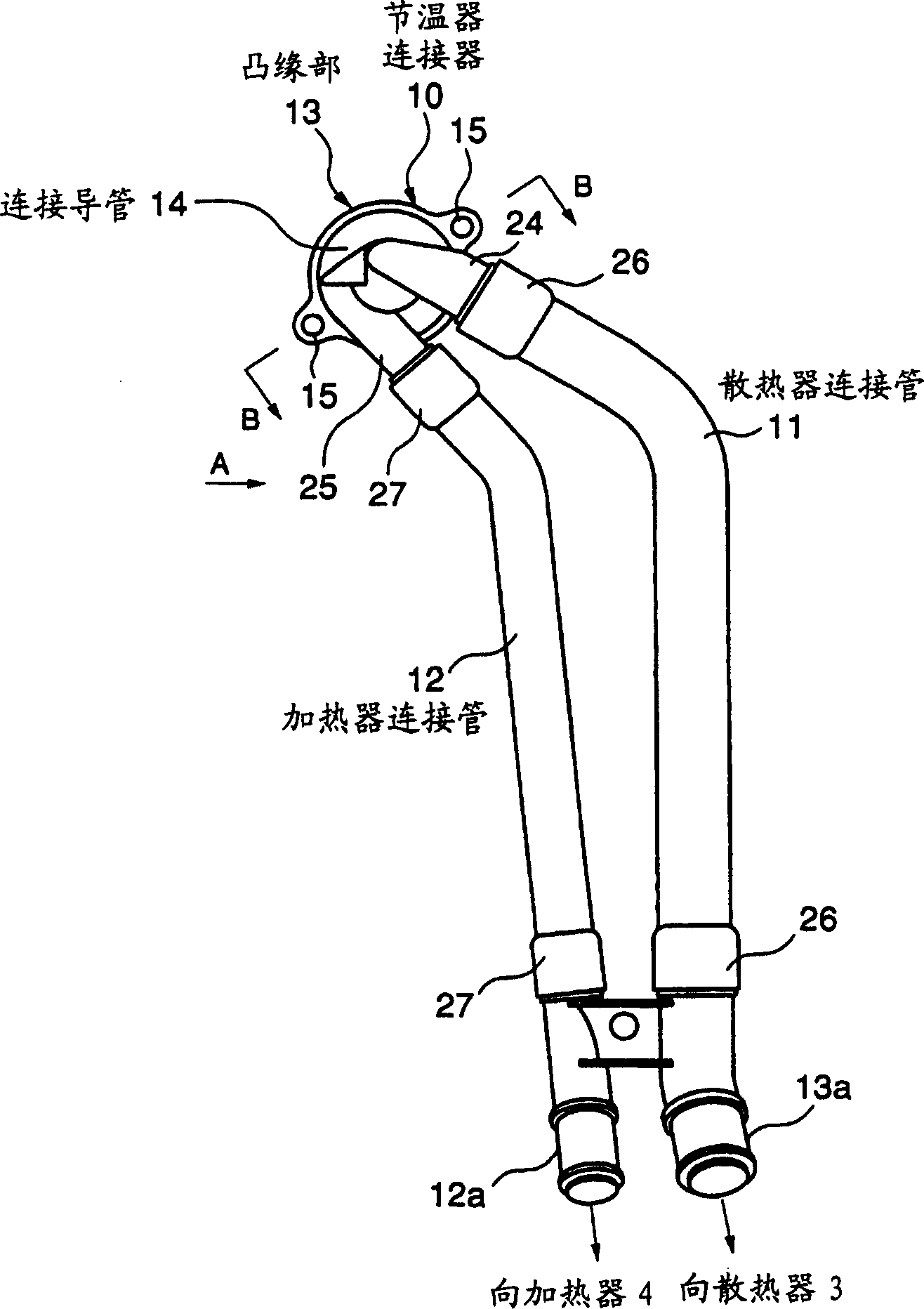
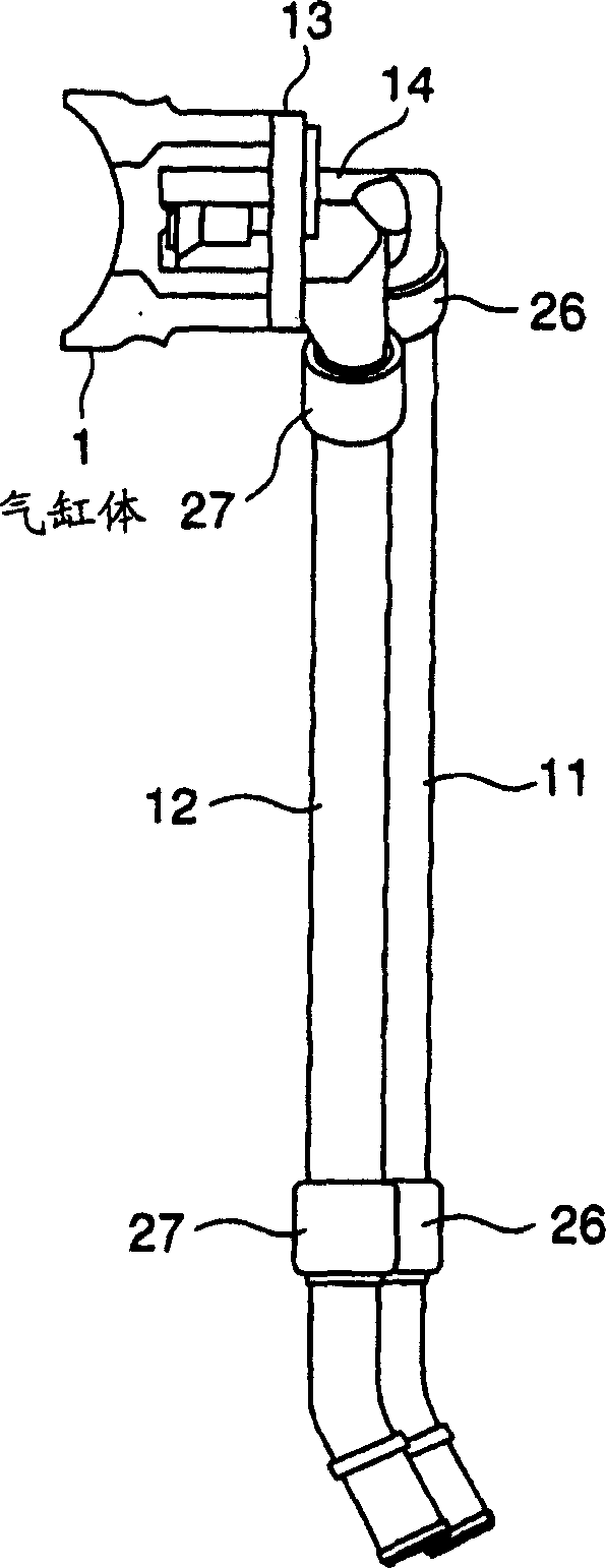
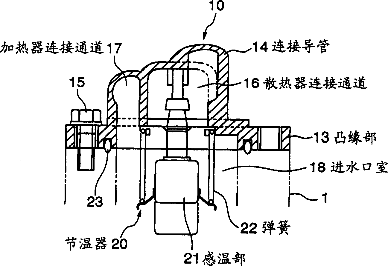
[0022] figure 1 is a front view of a thermostat connector in a cooling device of an engine according to an embodiment of the present invention, figure 2 Yes figure 1 A-direction view, image 3 is along figure 1 Sectional view of the B-B line. Figure 4 is a schematic diagram of a cooling device for an engine according to the present invention.

[0023] Figure 4 Shown is a cooling device for an engine according to the present invention, wherein 100 is an engine, 1 is a cylinder block of the engine, 2 is a cylinder head, 3 is a radiator, 4 is a heater, and 5 is a water pump.

[0024] Next...


PUM


Abstract

The invention provides a cooling device for an engine, which is provided with a thermostat at the cooling water outlet of the engine, and at the same time, the water inlet pipe of the heater is connected with the cooling water outlet to maintain the temperature sensitivity of the thermostat at a high degree, and make the thermostat The thermostat of the cooling water outlet and the connection structure of the radiator water inlet pipe and the heater water inlet pipe become simple and compact. According to the engine cooling device of the present invention, the cooling water flowing out from the engine is provided to the radiator through the thermostat and the radiator water inlet pipe, and at the same time provided to the heater through the heater water inlet pipe, it is characterized in that the cooling device includes a throttle Thermostat connector, the thermostat connector includes a connecting conduit, the connecting conduit is detachably assembled on the engine body, in the connecting conduit, the radiator connecting channel and the heater connecting channel are integrally formed, and the radiator connecting channel is set There is a thermostat and it is connected to the radiator water inlet pipe, while the heater connection channel is connected to the heater water inlet pipe.

Description

technical field [0001] The invention relates to a cooling device for an engine. The cooling device supplies cooling water flowing out of the engine to a radiator through a thermostat and a water inlet pipe of the radiator, and at the same time provides it to a heater through a water inlet pipe of a heater. Background technique [0002] The engine cooling device with a water outlet control thermostat is provided with a thermostat at the cooling water outlet of the engine, and the thermostat is built into the thermostat box, and the thermostat is used to open and close the radiator. At the same time as the cooling water channel of the water inlet pipe, the heater water inlet pipe is directly connected to the cooling water outlet of the engine, and the high temperature cooling water at the engine water outlet is provided to the heater. [0003] Patent Document 1 (Japanese Unexamined Patent Publication No. 6-173682) discloses an engine cooling device having such a water outlet c...

Claims


Application Information

Patent Timeline
IPC IPC(8): F01P3/20F01P7/16F01P11/00F01P11/04
CPCF01P7/16F01P11/00F01P11/04F01P2060/08
Inventor 吉原昭小木曾裕畅田丸敦士角谷浩阿部隆春
Owner MITSUBISHI MOTORS CORP
Why Eureka
Try Eureka