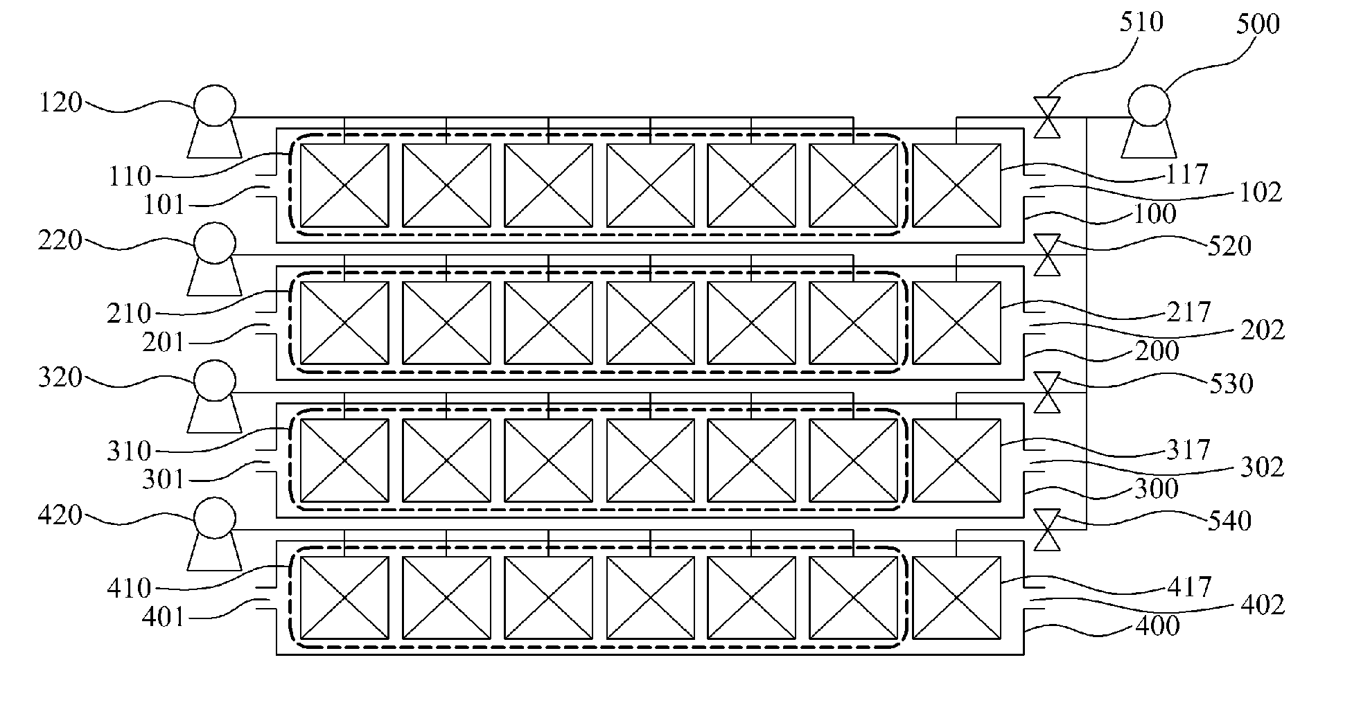

System and method for filtering

a filtering system and filtering technology, applied in the field of filtering systems and methods, can solve the problems of uneconomical, complex and uneconomical filtering system, adverse heat impact, etc., and achieve the effects of compact and simplified system structure, high recovery rate, and high recovery ra

Inactive Publication Date: 2015-03-17
KOLON IND INC
View PDF6 Cites 4 Cited by
  • Summary
  • Abstract
  • Description
  • Claims
  • Application Information

AI Technical Summary

Benefits of technology

The present invention is a system and method for filtering that can achieve a high recovery rate of 96% or higher, even when using a water bath for filtering. This means that no additional concentration apparatus or multi-stage filtration is needed, which makes the filtering process more compact and simple. Additionally, the filtering system improves the cleaning efficiency of the membrane while minimizing the interruption of the filtering operation.

Problems solved by technology

Furthermore, since the separation method using a membrane does not require a heating process, a membrane can be used with microorganism which is useful for separation process but may be adversely affected by heat.
In order to accomplish the total recovery rate of 96% or more, the filtering system shown in FIG. 1 requires more filtration capacity corresponding to the additional recovery rate, and requires the additional concentration apparatus 40, which is disadvantageous in that the filtering system becomes complicated and uneconomical.
However, this 2-stage filtering system is also problematic because it requires the additional structure for the second filtering process.

Method used


Image

  • System and method for filtering
  • System and method for filtering
  • System and method for filtering

Examples


first embodiment

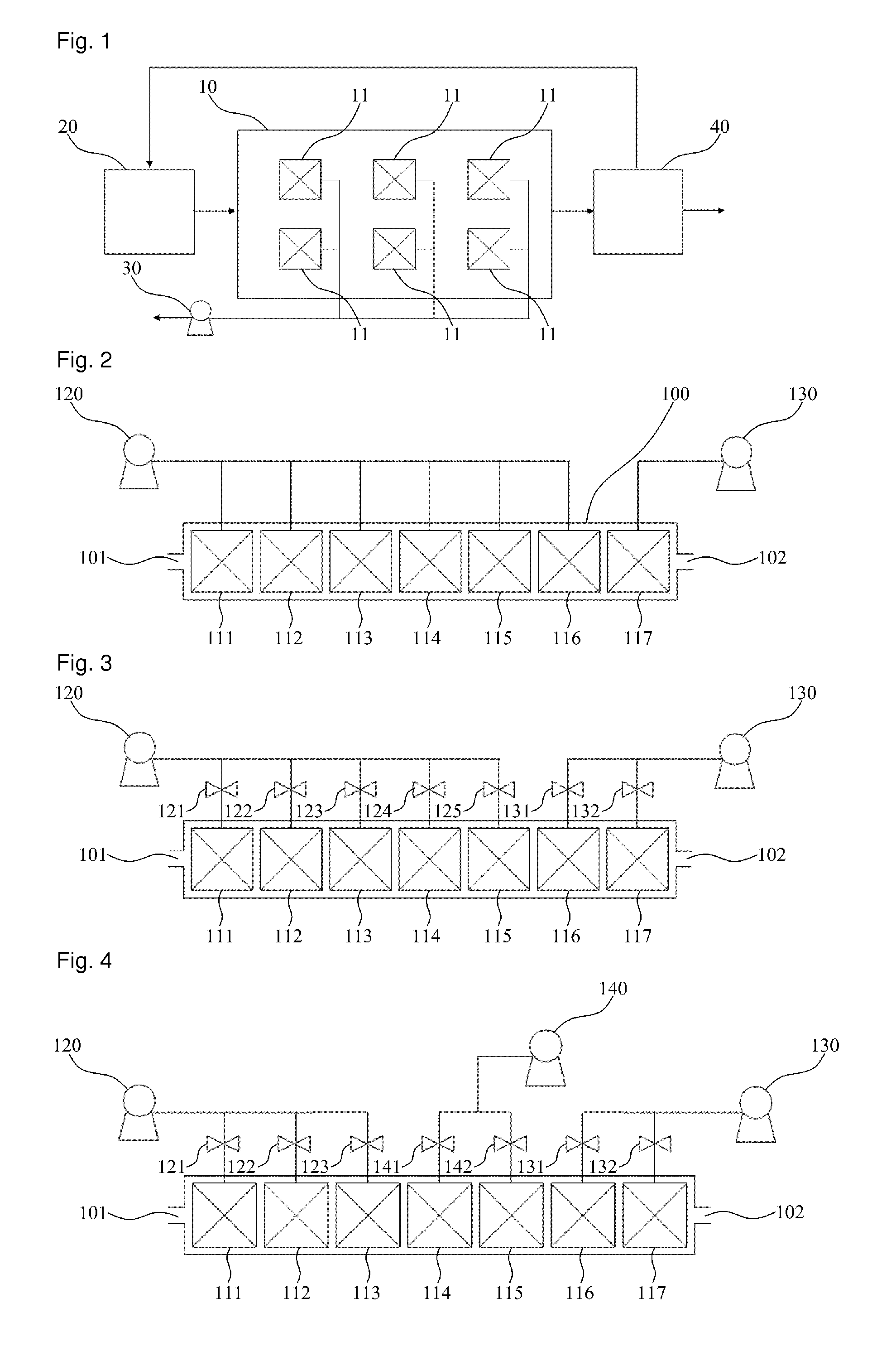
[0032]FIG. 2 illustrates a filtering system according to the present invention.

[0033]As shown in FIG. 2, the filtering system according to the first embodiment of the present invention is provided with a water bath 100 including an inlet 101 and a discharging hole 102. At this time, feed water to be treated is supplied to the inside of the water bath 100 through the inlet 101; and concentrated water remaining after filtering (hereinafter, “concentrated water”) is discharged out through the discharging hole 102.

[0034]Also, plural membrane cassettes 111 to 117 are submerged into the feed water contained in the water bath 100. According to the present invention, the plural membrane cassettes 111 to 117 are linearly arranged from the side of the inlet 101 to the side of the discharging hole 102; and the plural membrane cassettes 111 to 117 are tightly packed in the water bath 100. Accordingly, the feed water supplied to the inside of the water bath 100 sequentially passes through the li...

second embodiment

[0043]FIG. 3 illustrates a filtering system according to the present invention.

[0044]As shown in FIG. 3, a membrane cassette 116 is connected with a second pump 130 instead of a first pump 120, wherein the membrane cassette 116 neighbors to a membrane cassette 117 positioned nearest to a discharging hole 102. That is, the membrane cassette 116 carries out a water treatment operation using a negative pressure from the second pump 130. According to the second embodiment of the present invention, since a relatively-lower negative pressure is applied to the membrane cassette 116 for treating feed water with a relatively-larger impurity concentration, a lower flux is induced at the membrane cassette 116 so that it is possible to minimize the membrane fouling and to minimize damages to the membrane.

[0045]In addition, there are valves 131 and 132 which are respectively adjusted so as to open or close the paths between the respective membrane cassettes 116 and 117 and the second pump 130. E...

third embodiment

[0049]FIG. 4 illustrates a filtering system according to the present invention.

[0050]As shown in FIG. 4, the filtering system according to the third embodiment of the present invention includes plural membrane cassettes 111 to 117 linearly arranged in a water bath 100. In this case, a first negative pressure from a first pump 120 is provided to the membrane cassettes 111 to 113 positioned near to an inlet 101 at the front part of the water bath 100; a second negative pressure from a second pump 130 is provided to the membrane cassettes 116 and 117 positioned near to a discharging hole 102 at the rear part of the water bath 100; and a third negative pressure from a third pump 140 is provided to the membrane cassettes 114 and 115 positioned at the central part of the water bath 100. The third negative pressure is lower than the first negative pressure, and is higher than the second negative pressure. A flux order of the treated water obtained through the respective membrane cassettes ...


PUM

PropertyMeasurementUnit
heightaaaaaaaaaa
pressureaaaaaaaaaa
pressuresaaaaaaaaaa

Abstract

A system and method for filtering is disclosed, which is capable of accomplishing a filtering operation at a high recovery rate of 96% or more, and realizing a compact and simplified system structure, the system comprising a water bath including an inlet and a discharging hole, wherein feed water to be treated is supplied to the inside of the water bath through the inlet, and concentrated water is discharged out through the discharging hole; and plural membrane cassettes including first and second membrane cassettes submerged into the feed water contained in the water bath, wherein the first membrane cassette is positioned nearest to the inlet, and the second membrane cassette is positioned nearest to the discharging hole, wherein the first membrane cassette treats the feed water with a first impurity concentration; the second membrane cassette treats the feed water with a second impurity concentration; and the first impurity concentration is smaller than the second impurity concentration.

Description

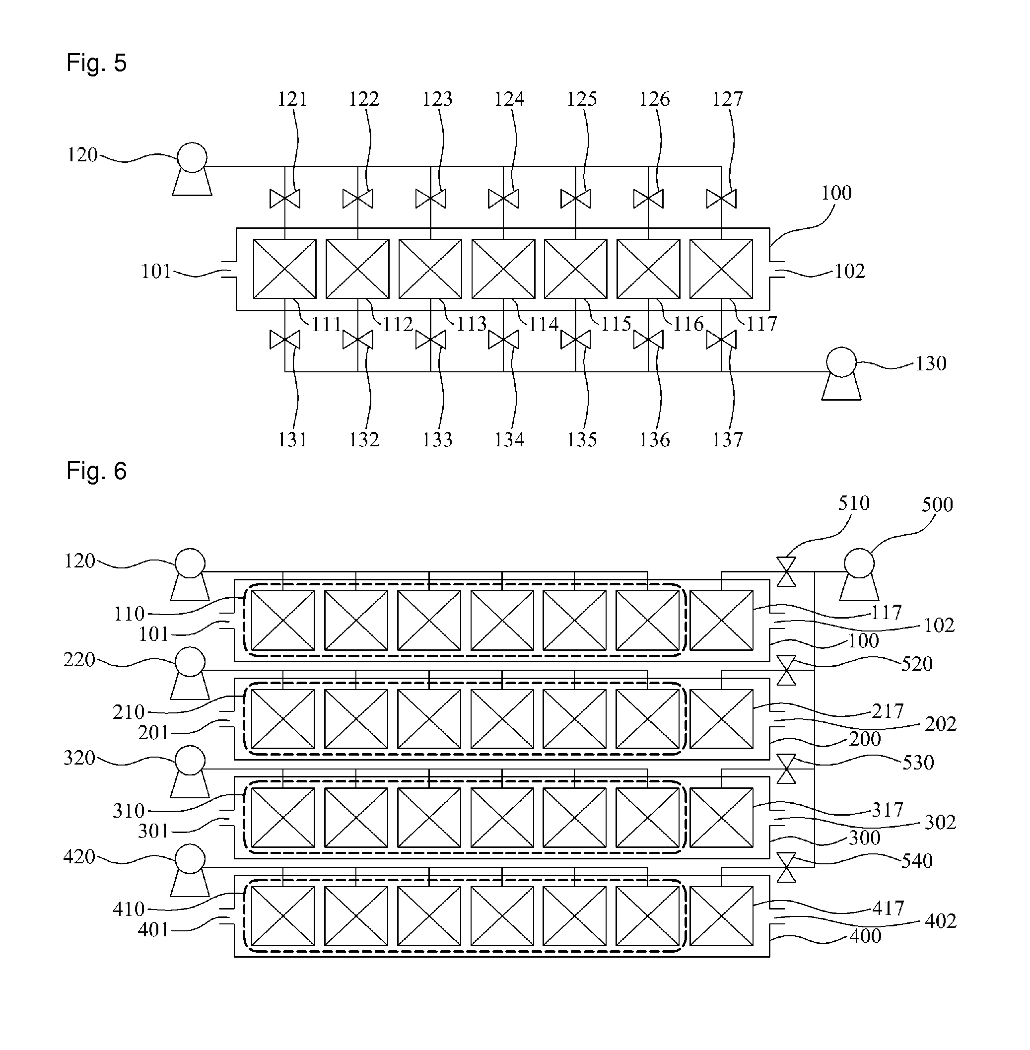
TECHNICAL FIELD[0001]The present invention relates to a system and method for filtering, and more particularly, to a system and method for filtering, which is capable of accomplishing a filtering operation at a high recovery rate of 96% or more, and realizing a compact and simplified system structure.BACKGROUND ART[0002]A separation method using a membrane has lots of advantages over the method based on heating or phase-changing. Among the advantages is high reliability of water treatment since the water purity required can be easily and stably satisfied by adjusting the size of the pores of a membrane. Furthermore, since the separation method using a membrane does not require a heating process, a membrane can be used with microorganism which is useful for separation process but may be adversely affected by heat.[0003]The membrane employing separation methods may include a method using a hollow fiber membrane module which comprises a bundle of hollow fiber membranes; and a method us...

Claims


Application Information

Patent Timeline
Patent Type & Authority Patents(United States)
IPC IPC(8): B01D61/18B01D61/22B01D61/20C02F1/00C02F1/44
CPCB01D61/18B01D61/20B01D61/22C02F1/44C02F2303/20B01D2315/06B01D2317/022B01D2317/04C02F2209/03B01D2311/14B01D65/02B01D61/00B01D63/00
Inventor LEE, KWANG-JIN
Owner KOLON IND INC
Learn More