Antenna testing method

A test method and antenna technology, applied in the direction of measuring electricity, measuring devices, measuring electrical variables, etc., can solve the problems of missed detection of defective antennas, inability to effectively ensure antenna quality, etc., to achieve the effect of ensuring quality

Inactive Publication Date: 2005-06-01
FOXCONN (KUNSHAN) COMPUTER CONNECTOR CO LTD +1
View PDF0 Cites 17 Cited by
  • Summary
  • Abstract
  • Description
  • Claims
  • Application Information

AI Technical Summary

Problems solved by technology

[0002] The existing antenna inspection method is to use a network analyzer to detect the voltage standing wave ratio of the antenna, but when the antenna is installed in the electronic device, due to insertion loss and feeder loss, etc., only the voltage standing wave ratio meets the requirements. During the use of the antenna, its gain value does not necessarily meet the requirements, so defective antennas will still be missed
[0003] The voltage standing wave ratio of

Method used


Image

  • Antenna testing method
  • Antenna testing method

Examples


Embodiment Construction

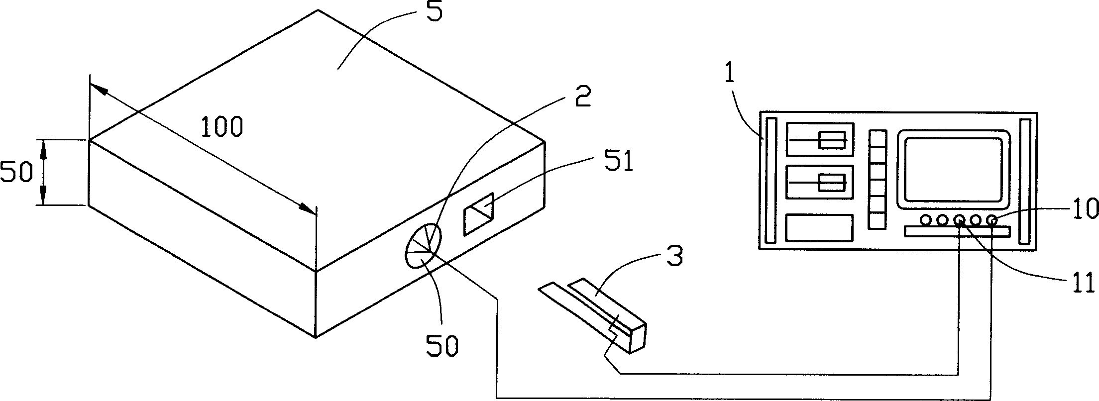
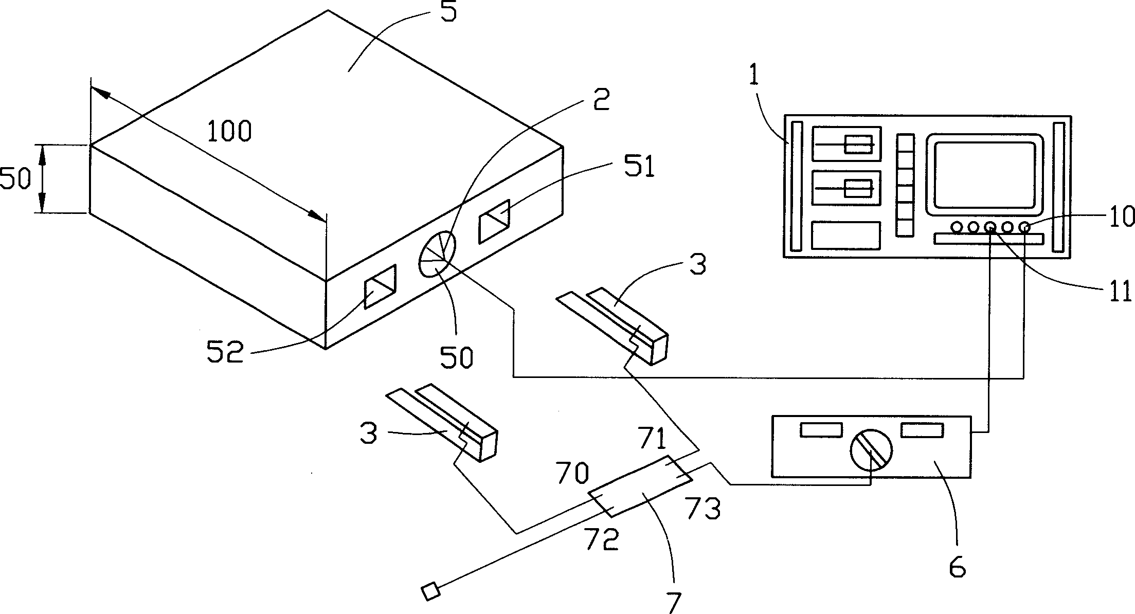
[0009] see figure 1 As shown, in this embodiment, a dipole antenna is selected as the reference antenna 2, a planar inverted-F antenna is selected as the antenna 3 to be tested, and various performance parameters of the reference antenna 2 are close to ideal values. The first port 10 of the network analyzer 1 is connected with the reference antenna 2 by wires (unlabeled), and the antenna 3 to be tested is connected with the second port 11 of the network analyzer 1, wherein the first port 10 is a signal output port, and the second Port 11 is a signal input port. A first receiving portion 50 and a second receiving portion 51 are opened on the non-metallic box 5 . The reference antenna 2 is placed into the first receiving portion 50 and fixed in the first receiving portion 50 . The antenna 3 to be tested is placed into the second receiving portion 51 and held in the second receiving portion 51 .

[0010] When the antenna 3 to be tested is tested, the first port 10 of the netwo...


PUM


Abstract

The antenna testing process includes the following steps: 1) selecting one network analyzer with the first port and the second port, one reference antenna, one non-metal box and one antenna to be tested; 2) setting on the non-metal box the first holding part and the second holding part; 3) setting the reference antennan and the tested antenna separately inside the first holding part and the second holding part; 4) connecting the reference antennan and the tested antenna separately to the first port and the second port of the network analyzer; and 5) transmitting reference signal via the first port to the reference antenna for emitting outwards, receiving the signal with the tested antennan and transmitting the signal to the second port, and obtaining the measurement result of the tested antennan in the network analyzer. The present invention has high antenna testing quality and efficiency.

Description

【Technical field】 [0001] The invention relates to an antenna test method, in particular to an antenna test method for measuring antenna gain. 【Background technique】 [0002] The existing antenna inspection method is to use a network analyzer to detect the voltage standing wave ratio of the antenna, but when the antenna is installed in the electronic device, due to insertion loss and feeder loss, etc., only the voltage standing wave ratio meets the requirements. During the use of the antenna, its gain value does not necessarily meet the requirements, so defective antennas will still be missed. [0003] The voltage standing wave ratio of the antenna body in the free state and fixed in the electronic device will be different, and the voltage standing wave ratio is only to measure the size of the signal rebound. When the loss of the transmission line is too large, the rebound energy will be caused by the mismatch of the antenna impedance. There will be a small amount of energy ...

Claims


Application Information

Patent Timeline
IPC IPC(8): G01R29/00G01R31/00H04B17/12
Inventor 林宪助洪振达
Owner FOXCONN (KUNSHAN) COMPUTER CONNECTOR CO LTD
Why Eureka
Try Eureka