Protective relay device

A relay device and system protection technology, which is applied to emergency protection circuit devices, circuit devices, emergency protection devices with automatic disconnection, etc., can solve problems such as wrong direction judgment and unbalanced component error

Inactive Publication Date: 2005-06-01
TOSHIBA FUEL CELL POWER SYST +1
View PDF0 Cites 3 Cited by
  • Summary
  • Abstract
  • Description
  • Claims
  • Application Information

AI Technical Summary

Problems solved by technology

[0010] However, in the method of judging the direction of the accident by measuring the unbalanced components of voltage and current in this way, if there

Method used


Image

  • Protective relay device
  • Protective relay device
  • Protective relay device

Examples


no. 1 Embodiment approach

[0092] refer to Figure 1-Figure 5 The protection relay device of the first embodiment will be described.

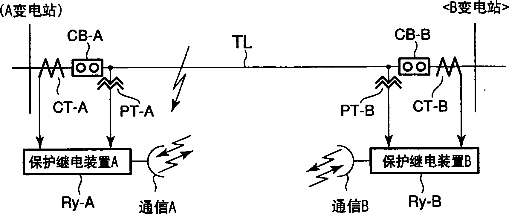
[0093] figure 1 It is a configuration diagram showing a power system in which a protective relay is installed.

[0094] figure 1 In , TL is the transmission line that is the protection target of A substation and B substation connected to the power system. In each substation A, B, protective relay devices Ry-A, Ry-B that obtain current (I) and voltage (V) through the current transformer CT and transformer PT and perform protection calculations are provided, respectively. These protective relay devices Ry-A, Ry-B use the communication units A, B to exchange disconnection permission signals for permitting disconnection commands to the counterpart circuit breakers CB-B, CB-A.

[0095] Since the protective relay devices Ry-A and Ry-B have the same structure, the internal structure of the protective relay device Ry-A will be described as a representative.

[0096] fig...

Deformed example 1

[0141] As a modified example of the accident judgment of the reverse-phase front relay 13F of the first embodiment, for example, the accident judgment is performed simply based on the phase difference.

[0142] As mentioned above, because in a frontal accident, -ΔV 2m and ΔI 2m They are basically the same phase, so if the phase difference is Φ, it can be judged by the following equation (9).

[0143] -ΔV 2m *ΔJ 2m

[0144] =|-ΔV 2m ‖ΔJ 2m |cosφ≥|-ΔV 2m ‖ΔJ 2m |X (9)

[0145] At this time, if X=0, the judgment action range is

[0146] - π 2 ≤ φ ≤ π 2

[0147] If set

[0148] X = 2 2 ,

[0149] then there is

[0150] - π 4 ≤ φ ≤ π 4

[015...

Deformed example 2

[0154] In Modification 2, the operation region for accident judgment is shifted. For example, if to Figure 7 -ΔV of the judgment action area shown 2m Substitute -(ΔV 2m -αΔV 2m ), then if Figure 8 As shown, get shifted by αΔV 2m characteristics. In addition, α is, for example, a constant.

[0155] Figure 8 It is an accident determination operation range diagram of Modification 2 showing the phase relationship between the reverse phase change amount voltage ΔV2 and the reverse phase change amount current ΔI2.

[0156] Here, the shift of the determination operation region is taken in the voltage direction, but if the calculation of the system swing is performed on the current, it may be shifted in the current direction.

[0157] This judgment method based on the reverse-phase front relay (DI2-D(F)) 13F of the first embodiment and the judgment method based on Modification 1 and Modification 2 focus on the amount of change in reverse-phase current and the change in reve...


PUM


Abstract

A protective relay device for a power system capable of reliably removing an accident point even for an accident within a protection interval that occurs during a system swing when a phase is lost. The swing detection circuit (PSB) (11) that detects the swing of the power system, the phase loss state detection circuit (LOP) (12) that detects the phase loss state, and the reverse phase change direction relay (front accident judgment part) (DI2-D ( F)) Each output of 13F is input into the AND circuit (15), and only in the system swing (in PSB action) in the phase loss state (LOP action) a system accident occurs, and the system accident is judged to be When the terminal (substation) is still in the forward direction (DI2-D(F) operates), a disconnection permission signal 16t is sent to the other terminal, and a disconnector disconnection signal ( 19 ) is output.

Description

technical field [0001] The present invention relates to a protective relay device, which can reliably remove the accident point and protect the power system even when an accident occurs in the swing accompanying the phase loss of the power system. Background technique [0002] The protective relay device for protecting the electric power system judges an accident occurring in the protected target range of the electric power system, operates a circuit breaker, and cuts off the accident part. The protection relay calculates the distance-measuring impedance based on the voltage and current input to the transformation equipment of the power system, and judges whether it is an accident within the protected object range based on its existence area (load area). In addition, in the case of an accident within the protection target range, a trip (trip) signal is sent to the trip switch. [0003] Figure 27 It is a diagram showing the relationship between the existence region (load re...

Claims


Application Information

Patent Timeline
IPC IPC(8): H02H3/48H02H3/26H02H3/34H02H3/38H02H3/40
Inventor 加濑高弘园部泰孝小笠原修
Owner TOSHIBA FUEL CELL POWER SYST
Why Eureka
Try Eureka