
Improved integrated sweeping, moping machine

An all-in-one, improved technology, applied in manual sweeping machinery, carpet cleaning, floor cleaning, etc., can solve the problems of low cleaning effect, large working resistance, complex structure, etc., to achieve small working resistance, improve effect, increase The effect of friction

Inactive Publication Date: 2011-02-02
王一川
View PDF0 Cites 2 Cited by
  • Summary
  • Abstract
  • Description
  • Claims
  • Application Information

AI Technical Summary

Problems solved by technology

Obviously, the drive chain of the technical solution of the patent application is too long, not only the structure is complex, but also the working resistance is large
In particular, the push rod is set on the mop roller, and the vertical force component of the push rod acts on the tail of the fuselage. The brushes installed at the front of the fuselage do not have enough pressure, and the cleaning effect is obviously reduced.

Method used


Image

  • Improved integrated sweeping, moping machine
  • Improved integrated sweeping, moping machine
  • Improved integrated sweeping, moping machine

Examples


Embodiment Construction

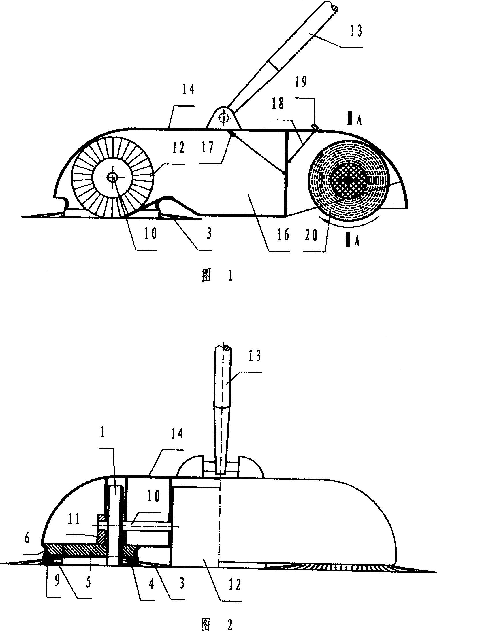
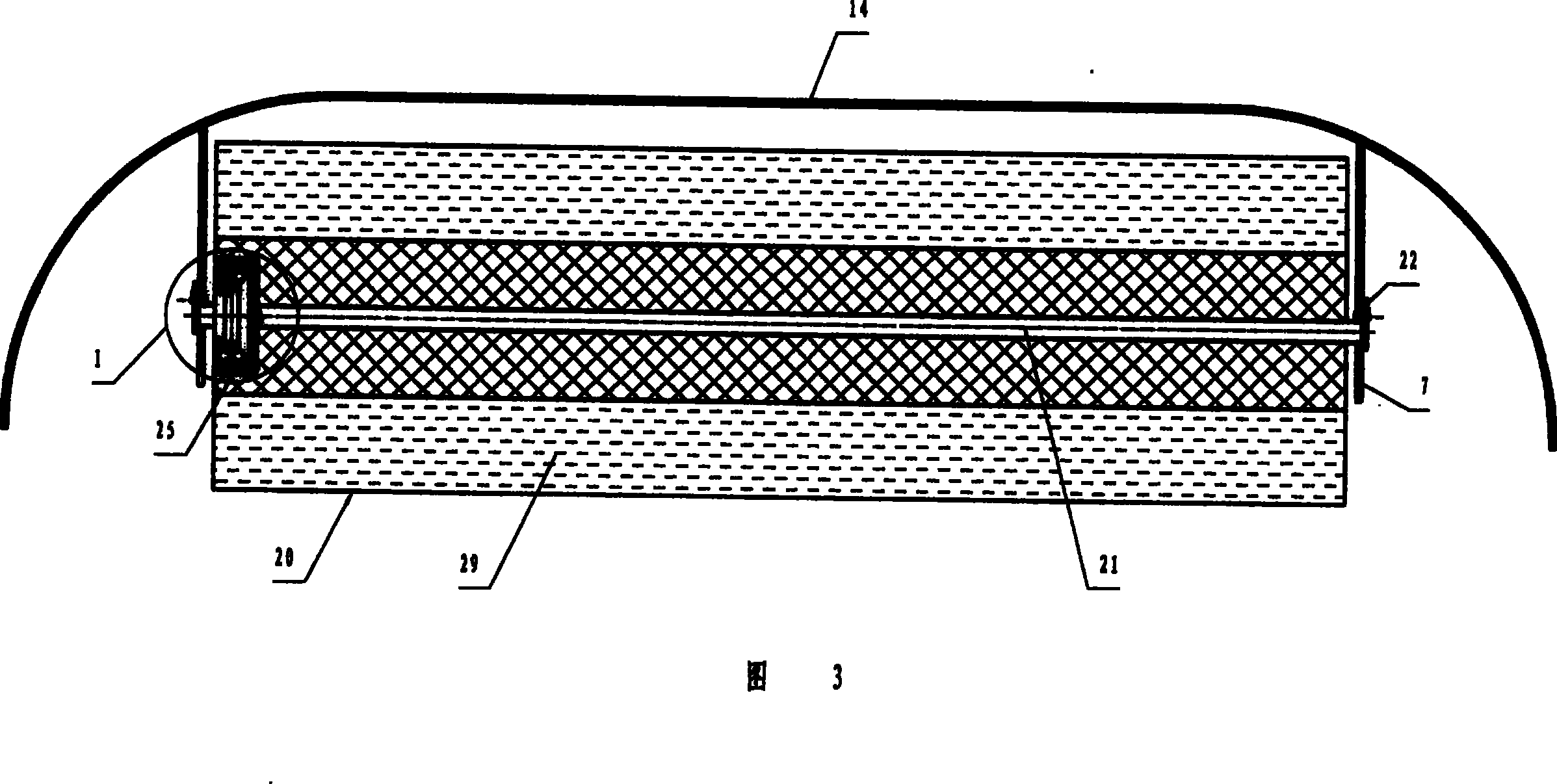
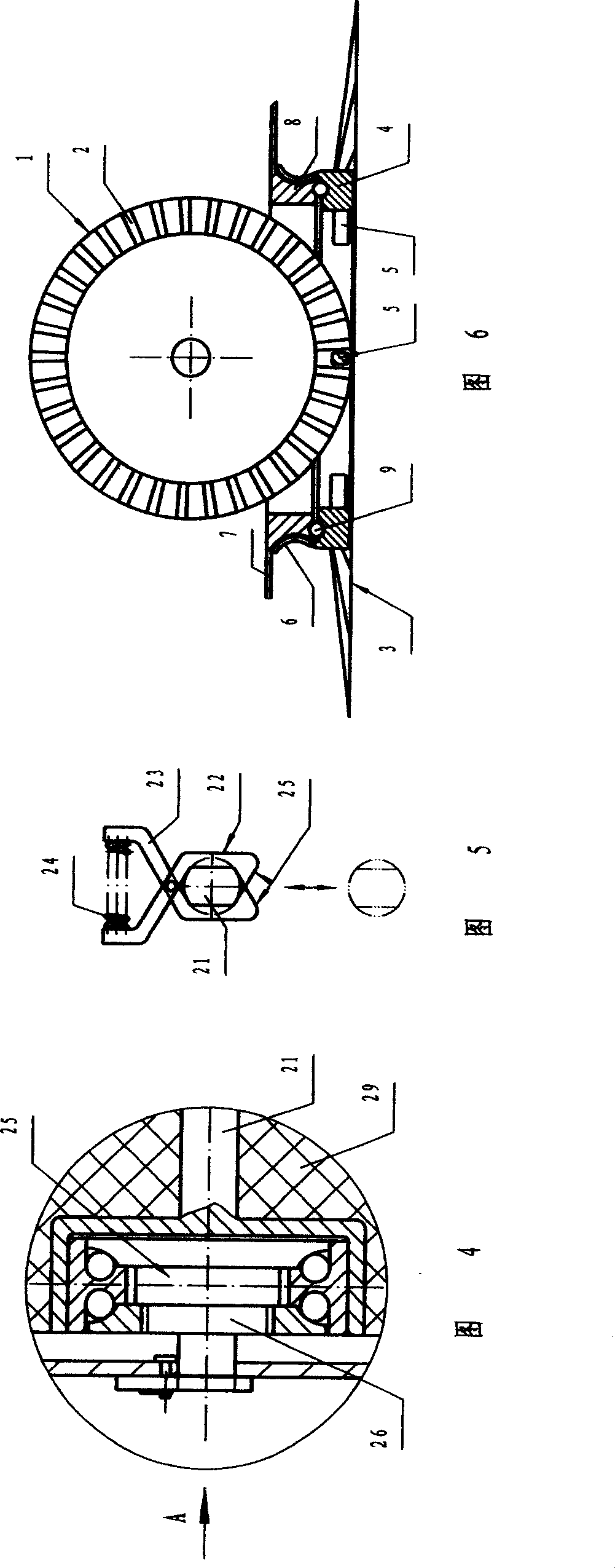
[0016] see figure 1 , figure 2 and Figure 6 The inner edge of the two front wheels 1 used as the drive wheel is provided with radial straight teeth 2, and the inner ring of the brush plate 4 of the disc side brush 3 is provided with radial straight teeth 2 with the same pitch as the inner edge of the front wheel 1. The protrusion 5, the protrusion 5 meshes with the straight teeth 2 to form a vertical transmission transmission mechanism; the edge of the upper end surface of the brush plate 4 is symmetrically provided with elastic claws 6, corresponding to the brush plate 4, the chassis 7 A pulley-shaped boss 8 is provided below, and the elastic claw 6 hangs the brush plate 4 on the boss 8. The lower end surface of the boss 8 and the upper end surface of the brush plate 4 are all provided with a raceway, and the rolling A steel ball 9 is placed in the track to form a rolling thrust bearing. The number of the elastic claws 6 is preferably singular in order to obtain a better...


PUM


Abstract

An improved sweeping-mopping machine is composed of a casing with a push bar on it, two front wheels, the central drum brush and two side disk brushes, which are driven by said front wheels, and a tail drum mop.

Description

Technical field: [0001] The invention relates to the field of cleaning machinery for floor coverings, and relates to a small household sweeping and mopping machine, in particular to a hand-push sweeping and mopping machine with rotary tools, which is suitable for floor coverings in homes and public places. sweeping and scrubbing. Background technique: [0002] I submitted to the State Intellectual Property Office a patent application for a "hand-push sweeping and mopping all-in-one machine" (application number: 200310002367.3). The tail of the push sweeper is formed by adding a roller mop. The power of the two disc side brushes and the middle roller brush is transmitted by the mop roller through a gear transmission mechanism and a belt transmission mechanism. Obviously, the transmission chain of the technical solution of this patent application is too long, not only the structure is complex, but also the working resistance is large. Especially the push rod is arranged on t...

Claims


Application Information

Patent Timeline
Patent Type & Authority Patents(China)
IPC IPC(8): A47L11/24A47L13/20
Inventor 王一川
Owner 王一川
Learn More