Centrifugal multi-blade fan

A multi-blade, centrifugal technology, used in non-variable volume pumps, components of pumping devices for elastic fluids, machines/engines, etc., can solve problems such as blade deformation, insufficient strength, deformation of auxiliary blades 101, etc. , to achieve the effect of preventing deformation, improving air transport capacity and noise suppression performance, and improving air transport capacity and noise suppression performance

Inactive Publication Date: 2005-06-08
SANDEN CORP
View PDF4 Cites 6 Cited by
  • Summary
  • Abstract
  • Description
  • Claims
  • Application Information

AI Technical Summary

Problems solved by technology

[0007] However, in the above structure, the strength of the blades 100, 101, especially the strength of the auxiliary blade 101 is insufficient, the rotation of the fan may ca...

Method used


Image

  • Centrifugal multi-blade fan
  • Centrifugal multi-blade fan
  • Centrifugal multi-blade fan

Examples


Embodiment Construction

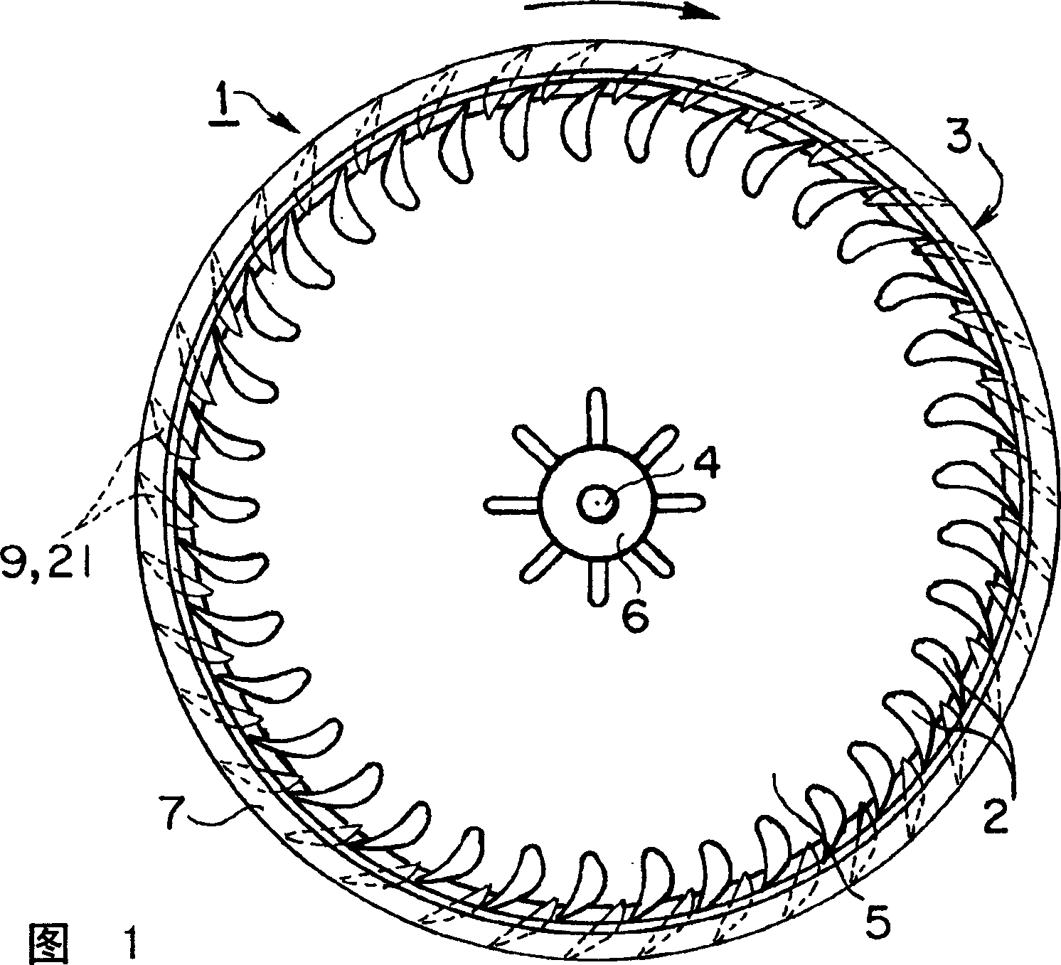
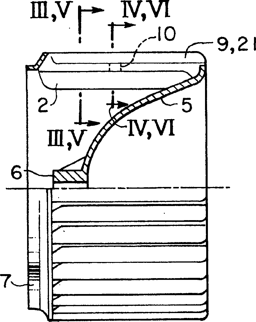
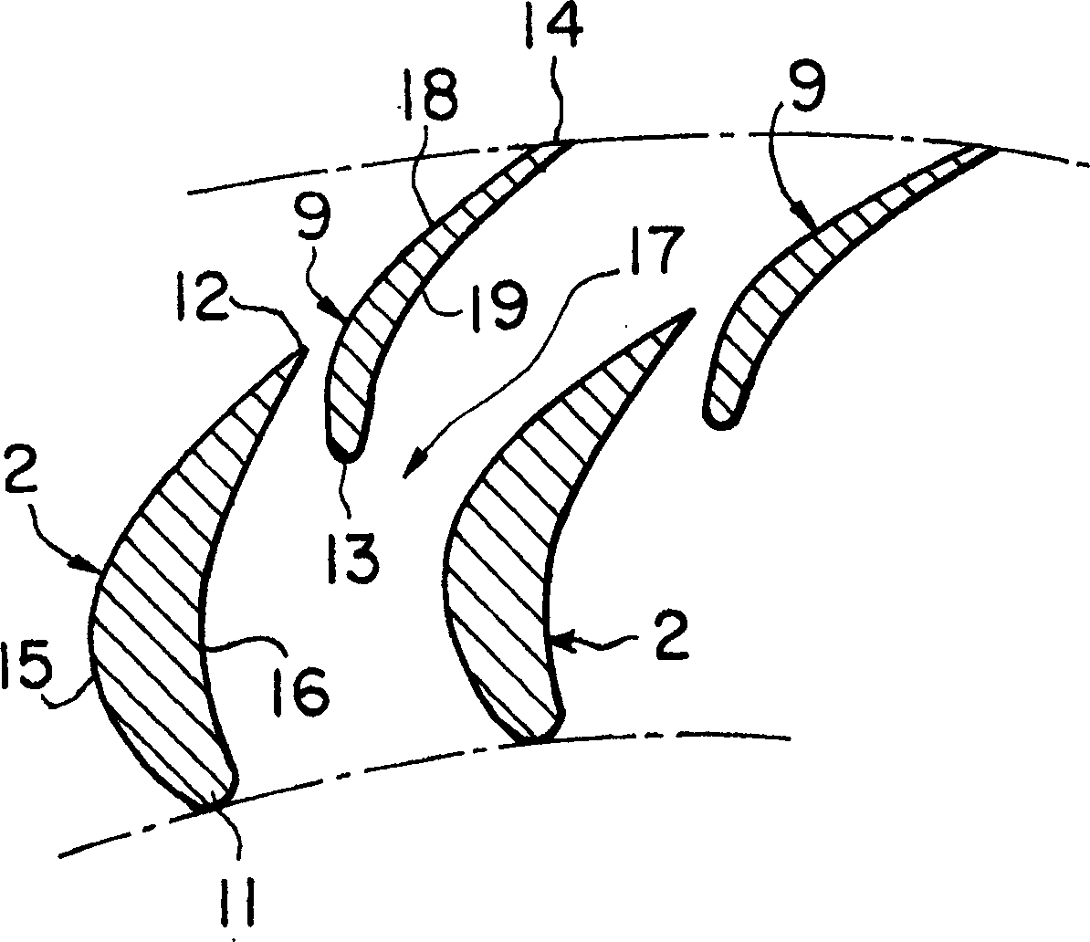
[0028] Figure 1 to Figure 4Shows a centrifugal multi-blade fan according to the first embodiment of the present invention. Among them, Figure 1 and figure 2 It is generally used to explain the second embodiment of the present invention described later. In Figure 1 and figure 2 Among them, the multi-blade fan part 3 of the multi-blade fan 1 has a plurality of main blades 2 and a plurality of auxiliary blades 9 . A plurality of blades 2 and 9 are arranged in a circumferential direction around the rotating shaft 4 . A disk-shaped drive plate 5 is arranged on the first ends of the blades 2 and 9 (on the anti-suction side of the fan 1 ) and is connected to all the blades 2 and 9 . A boss 6 is formed at a central portion of the drive plate 5 . The rotating shaft 4 is packed into the shaft sleeve 6, and by the rotation of the rotating shaft 5, the driving plate 5 and all the blades 2 and 9 rotate in a predetermined direction (the direction indicated by the arrow in FIG. 1). ...


PUM


Abstract

A centrifugal multi-blade fan includes a multi-blade fan section having a plurality of main blades arranged at radially inner positions and a plurality of auxiliary blades arranged at radially outer positions alternately arranged in a circumferential direction. Each adjacent main blade and each auxiliary blade are connected by a reinforcing rib, and the positive pressure surface of the auxiliary blade is preferably shaped as a plane. Therefore, the deformation of the auxiliary blade can be prevented, the basic function of the auxiliary blade can be ensured, and the airflow delivery capability and noise suppression performance of the fan can be improved.

Description

technical field [0001] The present invention relates to a centrifugal multi-blade fan, in particular to a centrifugal multi-blade fan with improved blade part structure, especially suitable for use in air-conditioning systems of vehicles and similar devices. Background technique [0002] The blowing capacity and noise of the blower are easily affected by the shape and structure of the fan blades and the shape of the reel of the casting. Therefore, these factors must be fully considered when designing the blower. [0003] In a multi-blade fan, since each blade arrangement is relatively short in the direction of airflow, it is difficult to form an airflow along the blades, and at the same time, the detachment of the airflow tends to generate vortices. Vortex noise due to the detachment of the airflow is the main cause of noise in multi-blade fans. A structure for reducing noise, for example, Japanese Patent JP-A-60-156997 proposes a blade shape, which is used to suppress the ...

Claims


Application Information

Patent Timeline
IPC IPC(8): F04D29/30
Inventor 北爪三智男
Owner SANDEN CORP
Why Eureka
Try Eureka