Clothes drier

一种干燥装置、衣物的技术,应用在干衣机领域,能够解决致冷剂压力差大、难恢复暖风温度、升温慢等问题,达到减轻负担的效果

Active Publication Date: 2005-06-15
PANASONIC CORP
View PDF1 Cites 46 Cited by
  • Summary
  • Abstract
  • Description
  • Claims
  • Application Information

AI Technical Summary

Problems solved by technology

[0003] But, in described existing device, heat source adopts the electric heater that heats up faster when efficiency is very high, but under the occasion that heat source adopts the heat pump device that contains compressor, because the temperature rise that compressor produces is higher than electric heater Slow, so it is difficult to immediately return to the original warm air temperature
In addition, for a period of time immediately after the compressor stops, the pressure difference between the refrigerants in the refrigeration cycle of the heat pump device is relatively large, so when the compressor is stopped and restarted continuously in a short period of time, the compressor may start. Failure situation

Method used


Image

  • Clothes drier
  • Clothes drier
  • Clothes drier

Examples


Embodiment 1

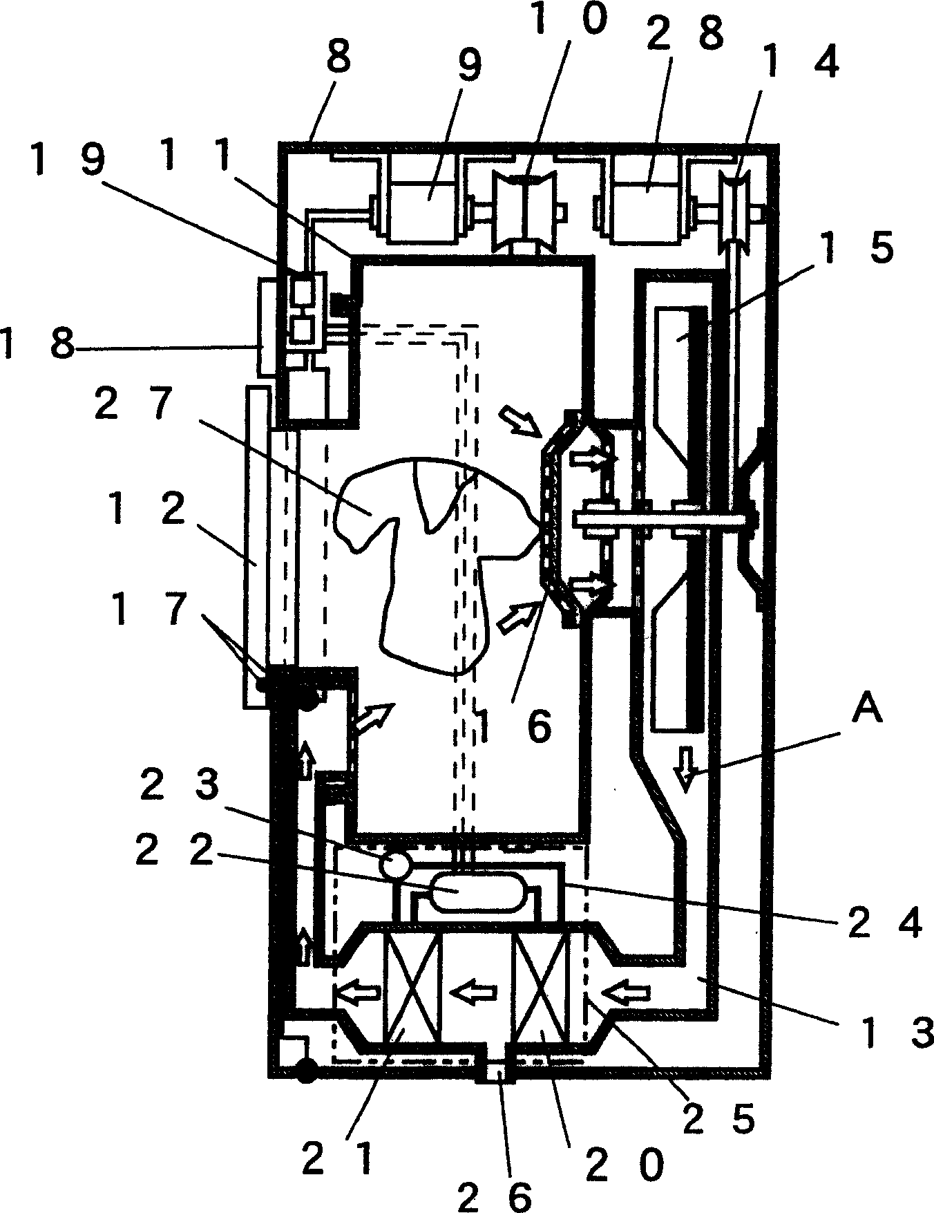
[0045] figure 1 It is a side sectional view of a clothes dryer equipped with the clothes drying device described in the first embodiment of the present invention. Such as figure 1 As shown in , the heat pump device 25 includes: a compressor 22 for compressing the refrigerant; a radiator 21 for releasing heat from the compressed high-temperature and high-pressure refrigerant; Pressure, thereby maintaining the pressure difference of the refrigerant capillary or other throttling device 23; The heat absorber 20 that takes away heat from the surroundings by the refrigerant that has been decompressed to a low pressure; and the above-mentioned components are connected so that The pipe 24 through which the refrigerant circulates.

[0046] Under the action of the blower 15, the air for drying clothes is guided from the drying room containing the clothes 27 to the rotating drum 11 of the stirring device through the air duct 13 to the heat absorber 20 and the heat radiator 21 of the ...

Embodiment 2

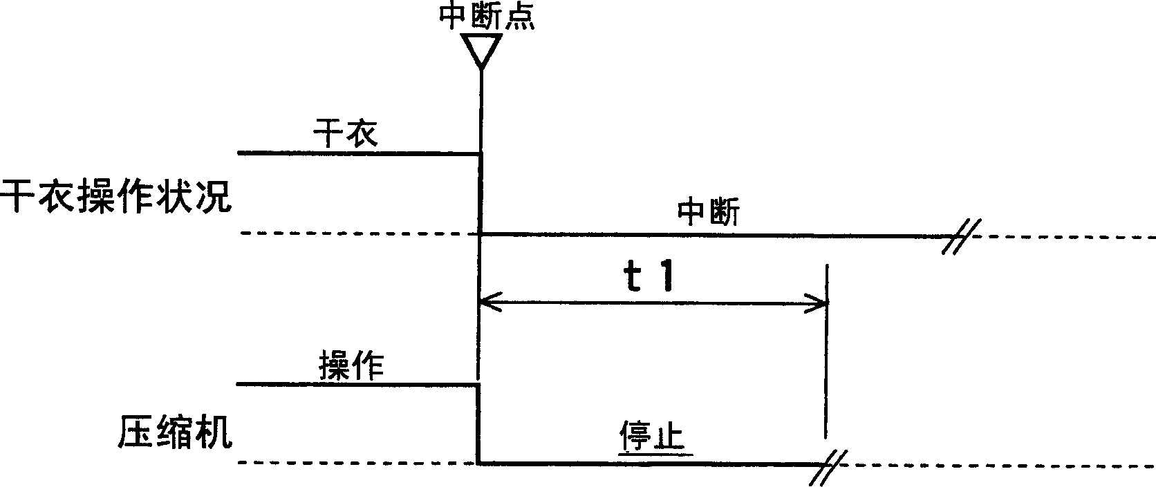
[0060] image 3 It is an operation timing chart when the drying operation of the clothes dryer equipped with the clothes drying apparatus according to the second embodiment of the present invention is interrupted. Here, since the basic operation and structure of the clothes dryer are the same as in Embodiment 1, a detailed description thereof will be omitted.

[0061] Such as image 3 As shown in , when the clothes drying operation is interrupted, the control device 19 restarts the compressor 22 after a predetermined time t1 has elapsed after the compressor 22 stops, and when the clothes drying operation is resumed.

[0062] In this way, by setting a prescribed stop time for the compressor 22, it is ensured that there is time to reduce the pressure difference of the refrigerant after the compressor 22 is stopped, thereby reducing the burden on the compressor 22 and preventing the compressor 22 from frequently operating in a short period of time. Stops and restarts are perfor...

Embodiment 3

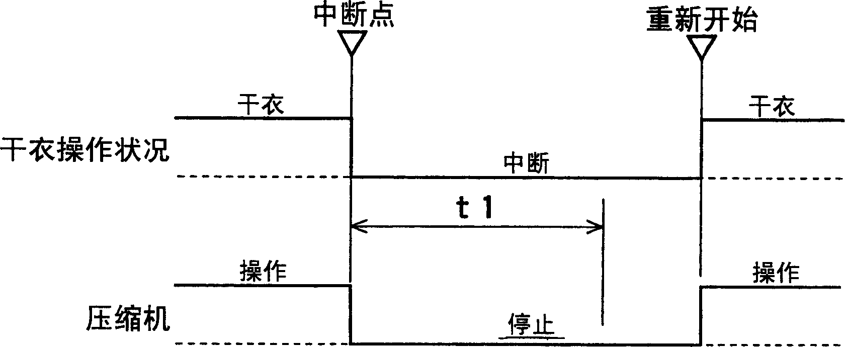
[0064] Figure 4 It is an operation timing chart when the drying operation of the clothes dryer equipped with the clothes drying apparatus according to the third embodiment of the present invention is interrupted. Here, since the basic operation and structure of the clothes dryer are the same as in Embodiment 1, a detailed description thereof is omitted here.

[0065] Such as Figure 4 As shown in , the drying operation starts before the predetermined time t1 elapses after the compressor 22 stops. Also in such a case, the control device 19 restarts the operation of the compressor 22 after the predetermined time t1 has elapsed.

[0066]In this way, by ensuring that the stop time of the compressor 22 reaches the prescribed time t1, the load on the compressor 22 can be reduced, and thus it is possible to cope with the interruption of the drying operation.


PUM


Abstract

A clothes drying apparatus includes a heat pump mechanism (25), an air path (13) for guiding drying air into a drying drum (11) accommodating therein clothes (27), a blower (15) for supplying drying air to the air path (13), and a controller for controlling a driving of a compressor (22), wherein the controller operates the blower (15) and the compressor (22) during a drying operation; stops the compressor (22) in case the drying operation is suspended; and operates, in case the drying operation is resumed, the compressor (22) after a certain time period has elapsed since the compressor (22) had stopped. In case employing the heat pump mechanism (25) having the compressor (22) as a heat source, it is possible to reduce a load on the compressor (22) and allow temperature of warm air to rapidly return by using the heat pump mechanism (25). <IMAGE>

Description

technical field [0001] The present invention relates to a clothes dryer capable of drying various kinds of clothes, or in other words, a clothes drying device provided in a washer-dryer capable of washing and drying clothes in the same tub. Background technique [0002] In the existing clothes dryer, during the drying process, when the user opens / closes the door to put in / take out clothes, etc., the clothes drying operation will be interrupted (paused), and the heating device, the blowing device and The stirring device will also all stop operation (one example wherein can refer to Japanese Patent Publication No. 8-182897). Figure 19 Shown in the existing clothes dryer described in above-mentioned document. Such as Figure 19 As shown in , this existing clothes dryer is provided with: a rotating drum 1 that simultaneously plays the role of a drying chamber for loading clothes and performing drying operations and an agitating device; A heat-exchanging double-wing fan 2 that ...

Claims


Application Information

Patent Timeline
Patent Type & Authority Applications(China)
IPC IPC(8): D06F58/20D06F58/24D06F58/28
CPCD06F58/206D06F2103/50D06F2105/26D06F2103/68D06F2105/62D06F2105/50D06F58/50D06F2103/40D06F2105/30D06F58/38
Inventor 中本重阳薮内秀隆野嶋元田中优行
Owner PANASONIC CORP
Why Eureka
Try Eureka