Two degrees of freedom moving planar parallel mechanism

A degree of freedom and parallel technology, applied in the direction of manipulators, program-controlled manipulators, manufacturing tools, etc., can solve the problems of high manufacturing costs and achieve the effects of low manufacturing costs, reduced movement quality, and light weight

Inactive Publication Date: 2005-06-22
GUANGDONG UNIV OF TECH
View PDF0 Cites 25 Cited by
  • Summary
  • Abstract
  • Description
  • Claims
  • Application Information

AI Technical Summary

Problems solved by technology

For example, in the automated production lines of light industry, medicine, food and electronics industries, such as the welding head mechanism of the chip bonder, the wafer feeding mechanism, and the placement mechanism of the S

Method used


Image

  • Two degrees of freedom moving planar parallel mechanism

Examples


Embodiment Construction

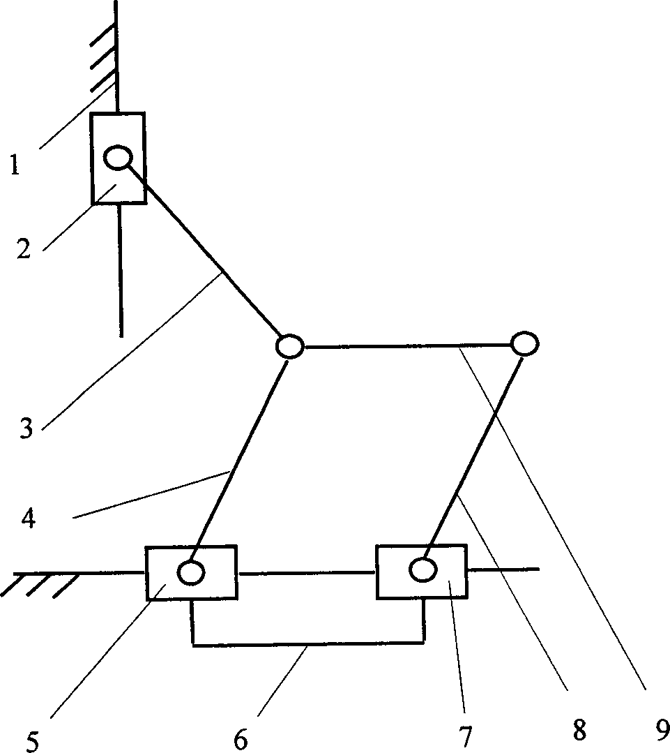
[0013] The preferred solution for the implementation of the present invention is given below and described in conjunction with the accompanying drawings.

[0014] The overall structure of this embodiment is as figure 1 As shown, the fixed platform 1 is composed of two guide rails perpendicular to each other. The two guide rails are perpendicular to each other because the welding head is required to have translational motion in these two directions when it is working. If the movement is completed by synthetic motion, the two The guide rail can also be non-vertical, and the connecting plate 6 connects the driving slider 5 and the driven slider 7, so that the driving slider 5 and the driven slider 7 have the same motion, respectively by the slider 2, the connecting rod 3 and the driving slider 5. The motion branch chain composed of connecting plate 6, driven slider 7, connecting rod 4 and connecting rod 8 connects the fixed platform 1 and the moving platform 9. The structure of t...


PUM


Abstract

This invention belongs to industry robot field and provides a two free degree plane parallel structure, which comprises fixed platform and moving platform and the moving chain composed of slide block and connection bar. The fixed platform comprises two vertical guide rails. The connection plate connects the drive slide block and passive block. The kinematic pair between slide blocks, drive slide block, passive block and fixed platform is moving pair and other kinematic pair between the rest parts is rotation pair.

Description

technical field [0001] The invention belongs to the field of industrial robots, and in particular relates to a two-degree-of-freedom moving plane parallel mechanism, which is especially suitable for a welding head mechanism of a wafer bonding machine, a key equipment of a semiconductor post-process production line. Background technique [0002] The parallel mechanism is a closed-loop kinematic system composed of multiple parallel chains, that is, one end of multiple kinematic chains is connected to a terminal operator with multiple degrees of freedom at the same time. The parallel mechanism has the following advantages: high stiffness-to-weight ratio; high load-to-weight ratio; small error and high precision; it is easy to place the drive motor on the machine base, which reduces the motion load and can move at high speed; in position solving , the reverse solution of the parallel mechanism is easy; the structure is simple and the degree of modularization is high. [0003] I...

Claims


Application Information

Patent Timeline
IPC IPC(8): B25J9/08
Inventor 陈新温兆麟吴小洪李克天何汉武
Owner GUANGDONG UNIV OF TECH
Why Eureka
Try Eureka