Measuring method for migration rate in unimolecular level

A technology of migration speed and measurement method, which is applied in the direction of material excitation analysis, fluorescence/phosphorescence, etc., can solve the problems of large sample volume and long time-consuming, and achieve the effect of reducing usage and fast speed

Inactive Publication Date: 2005-06-22
DALIAN INST OF CHEM PHYSICS CHINESE ACAD OF SCI
View PDF0 Cites 4 Cited by
  • Summary
  • Abstract
  • Description
  • Claims
  • Application Information

AI Technical Summary

Problems solved by technology

The disadvantage is that it requires a large amount of sample and takes a long time (short minutes, long hours).

Method used


Image

  • Measuring method for migration rate in unimolecular level
  • Measuring method for migration rate in unimolecular level
  • Measuring method for migration rate in unimolecular level

Examples


Embodiment

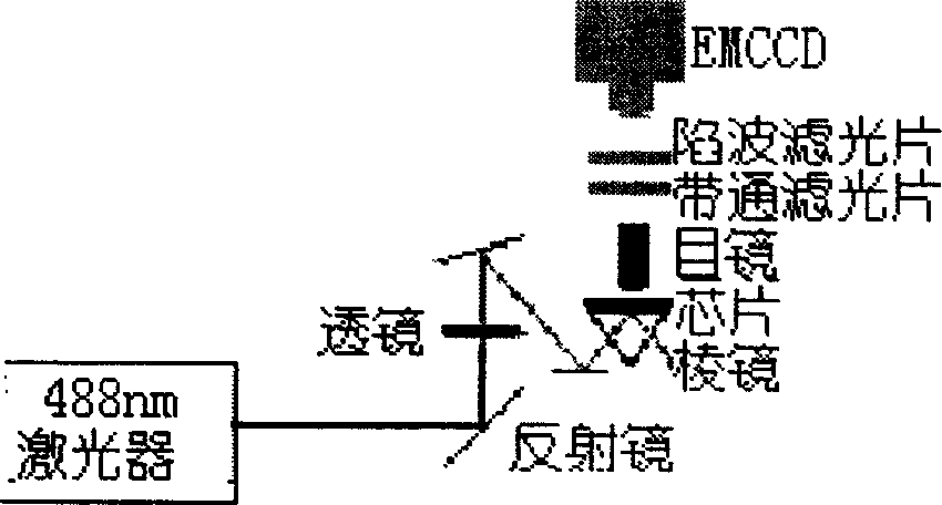
[0020] A quartz chip is placed on the hypotenuse of a fused silica rectangular prism. Put a drop of immersion oil between the chip and the prism. Before each detection, use 10uL NaOH (1M), secondary water and 10uL Gly-Gly buffer to flush the channel by vacuuming the buffer pool at one end. The migration of molecules in channels can be driven by electromotive force or pressure. The diagram of the experimental setup is shown in figure 1 . Chips and prisms are placed on the fluorescence microscope stage. The continuous laser light emitted by the water-cooled argon ion laser is focused in the channel of the chip through a series of mirrors, 20 cm focal length lenses and prisms (see Figure 4 ), total reflection on the surface of the microchannel. The laser power to the front of the prism is between 5mW and 140mW. Fluorescence emitted by the sample is collected by the microscope objective. A 488nm holographic notch filter and / or a 514nm filter is placed between the EMCCD and...


PUM


Abstract

This invention provides a test method for horizontal migration velocity of monomolecular. A laser emits continuous lasers to focus on an under-test sample in the chip channel via an optical system, the activated fluorescence is collected on CCD by a micro-object glass, characterizing that the exposing time is greater than 8ms dividing the obtained trace length to get the migration velocity. Since fluorescent molecules still migrate during data collection time, fluorescent photons respond at the places corresponding to the DNA molecular moving positions on EMCCD chip to form a molecular migration trace.

Description

Technical field: [0001] The present invention mainly relates to a method for measuring migration velocity at the single molecule level. Background technique: [0002] In recent years, single-molecule optical detection technology has developed rapidly [Gai Hongwei, Bai Jiling, Lin Bingcheng, Analytical Chemistry 2002, 30(7): 869-874]. Compared with conventional ensemble analysis, this technology not only has the highest sensitivity, but also in the following several This aspect also has advantages: (1) It can give the distribution of a certain physical quantity in the whole research system, while the ensemble method obtains the system average value, so a lot of individual information is lost; (2) It can detect some specified The changing behavior of molecules over time is truly real-time, and a large number of molecules are actually in different time states in the results obtained by ensemble averaging; (3) it will reveal the difference between individual behavior and the ave...

Claims


Application Information

Patent Timeline
Patent Type & Authority Applications(China)
IPC IPC(8): G01N21/64
Inventor 盖宏伟於林芬马银法林炳承
Owner DALIAN INST OF CHEM PHYSICS CHINESE ACAD OF SCI
Why Eureka
Try Eureka