Rotation and torsional vibration compound movement mechanism based on planetary drive with small teeth difference

A technology of compound motion and transmission mechanism, applied in the field of mechanical transmission, can solve the problems of speed ratio limitation, poor manufacturability of composite mechanism assembly and manufacturing structure, complex structure, etc. compact effect

Inactive Publication Date: 2005-06-29
XIAN UNIV OF TECH
View PDF0 Cites 5 Cited by
  • Summary
  • Abstract
  • Description
  • Claims
  • Application Information

AI Technical Summary

Benefits of technology

This new design simplifies the movement of parts within an engine's mechanical system without adding extra weights or making them bigger than usual. Its technical effect lies in improving its efficiency at transmitting rotational motion through gears that have small teeth on their outer surface. Additionally, this device allows for quicker and more precise changes over time due to its ability to rotate quickly and accurately around multiple axes simultaneously.

Problems solved by technology

In current technical problem addressed in this patents relates to achieving efficient use of energy from multiple different types of movement (rotation) or transformation). Current systems have limitations with regard to their ability to achieve both smoothly rotate at very fast speeds while also generating significant force without causing excessive noise during operation due to complicated structures.

Method used


Image

  • Rotation and torsional vibration compound movement mechanism based on planetary drive with small teeth difference
  • Rotation and torsional vibration compound movement mechanism based on planetary drive with small teeth difference
  • Rotation and torsional vibration compound movement mechanism based on planetary drive with small teeth difference

Examples


Embodiment 1

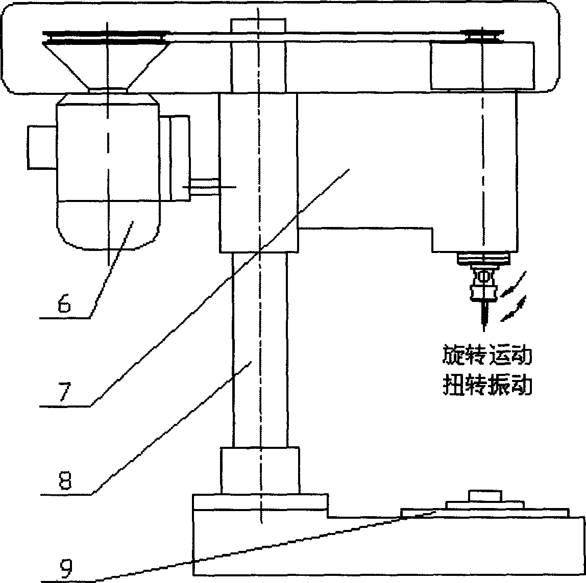
[0033] Embodiment 1: The mechanism of the present invention is used in the headstock structure of a vibration tapping and reaming desktop machine.

[0034] see image 3 : Ordinary tapping and reaming process is that the tap or reamer installed on the main shaft only performs low-speed rotary motion, the cutting speed is low, the cutting torque is large during the machining process, the tool life is short, the cutting fluid lubrication effect is poor, and the tapping thread and Reaming accuracy is low. Vibration tapping and reaming are based on traditional tapping and reaming methods, artificially applying regular torsional vibration to the tap or reamer to form pulsed intermittent cutting, thereby increasing the instantaneous cutting speed of the tap or reamer, making The tap or reamer repeatedly presses the machined surface in the process of reciprocating advance and retreat, which reduces the cutting force, improves the lubrication effect of the cutting fluid, and improves ...

Embodiment 2

[0035] Embodiment 2: the mechanism of the present invention is used in the special equipment structure of vibratory grinding process

[0036] see Figure 4: Ordinary cylindrical grinding spindle box 10 only provides low-speed rotary motion, and the workpiece 13 installed between the spindle box 10 and the tailstock 14 can only perform low-speed rotation under the action of the dial 11, and the high-speed rotating emery wheel 12 completes the grinding In the grinding operation, since the workpiece 13 is constantly rotating and longitudinally fed with the workbench, there is always a large specific pressure between the grinding wheel 12 and the workpiece 13, the grinding temperature is high, the workpiece is easily burned, and the grinding efficiency is low. In the present invention, a new vibration grinding method can be formed by converting the unidirectional rotary motion of the spindle box of an ordinary cylindrical grinder into a composite motion of rotation and torsional v...


PUM


Abstract

The invention discloses a transmission mechanism for realizing compound motion of rotation and torsional vibration based on transmission with few tooth differences. The motion input is realized by the eccentric shaft connected to the power source; the motion conversion mechanism is realized by the external gear that is free from the eccentric shaft and the internal gear that meshes with the external gear; the motion output mechanism is realized by the fork pin that is fixedly connected with the external gear 1. A compound motion output element with a shift fork slot plugged in with the shift fork pin is realized. Among them, the eccentric shaft, external gear, and internal gear form a standard transmission with few tooth differences, which converts the input rotary motion with a speed of n (rpm) into a low-speed revolution with a speed of n/i (rpm) and a speed of n (rpm), radius of gyration It is the high-speed rotary plane motion of e1; the fork pin and the compound motion output element realize the conversion of the compound motion of the external gear into the compound motion of rotation and torsional vibration and output it. Compared with the existing transmission scheme, the structure of the mechanism is greatly simplified, the matching range of motion parameters is wider, and it can be widely used in vibration tapping, vibration drilling, vibration grinding and other mechanical processing technical fields.

Description


Claims


Application Information

Patent Timeline
Owner XIAN UNIV OF TECH
Why Eureka
Try Eureka