Optical alignment quick positioning tacking device

An optical collimation and fast technology, applied in the parts, instruments, casings and other directions of the instrument, can solve the problem that the multi-band comprehensive photoelectric performance detection device cannot be used, and the adjustment or positioning of multiple optical devices or instruments cannot be realized. problems, to improve work performance and combat effectiveness, and to achieve the effect of installation and disassembly

Inactive Publication Date: 2005-06-29
ORDNANCE TECH RES INST OF THE GENERAL ARMAMENT DEPT PLA
View PDF0 Cites 8 Cited by
  • Summary
  • Abstract
  • Description
  • Claims
  • Application Information

AI Technical Summary

Problems solved by technology

However, the existing connection and positioning device cannot meet the needs of the multi-band comprehensive photoelectric performance detection device because it cannot realize the adjustment or positioning of any position of multiple optical devices or instruments.

Method used


Image

  • Optical alignment quick positioning tacking device
  • Optical alignment quick positioning tacking device
  • Optical alignment quick positioning tacking device

Examples


Embodiment Construction

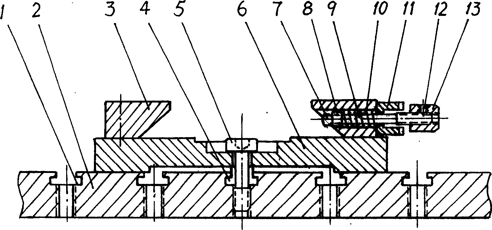
[0015] like figure 1 , Figure 4 Shown, on the planar workbench frame 2, be provided with equidistant some inverted T-shaped slots 1 perpendicular to each other vertically and horizontally, and screw holes are provided on the plate surface at the junction of the vertical and horizontal slots. Screw holes are preferably opened at each junction, so that the movable base can be fixed at any position on the workbench frame.

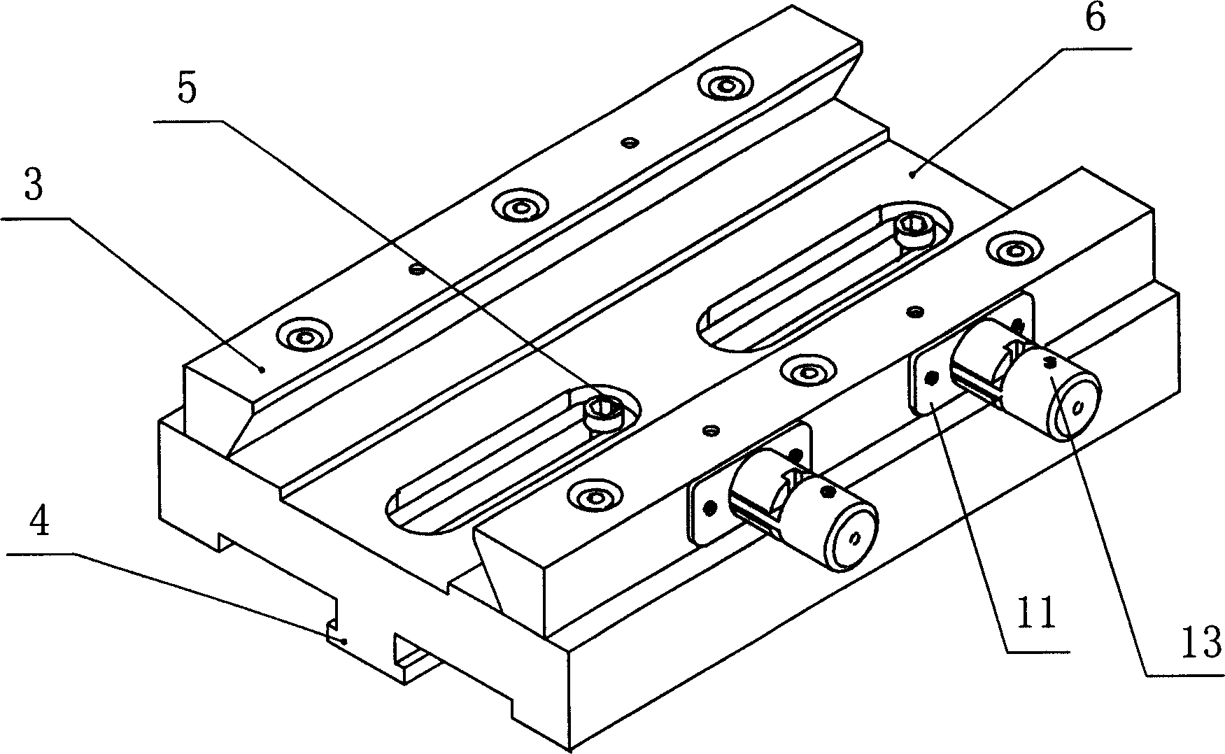
[0016] like figure 1 , image 3 As shown, the movable base 6 is a rectangular plate body, and a lower guide rail 4 with an inverted T-shaped cross section is formed on the center line of symmetry of its bottom surface. The bar slot is opened on the center line of symmetry of the movable base 6, and its width should be less than the nut diameter of the fastening screw 5. In order to ensure the smooth flow of the top surface of the movable base, a stepped groove is provided on the top of the bar-shaped slot hole, so that the top surface of the nut is submer...


PUM


Abstract

This invention discloses an optical calibration rapid position tight screw device, which has the following structure: to open several crossed car imbed groove on its plane platform; to set screw holes in the crossing area of the groove; to plug the down guide rail on the mobile socket into the shape groove; to open a support screw cap bar hole on the mobile socket; the bar groove is relative to down guide rail; to fix coattail groove upper guide rail on the two sides of the top surface of the mobile socket; to fix an elastic locking mechanism on the upper guide rail.

Description

technical field [0001] The invention relates to a mechanical connection and positioning device of an optical device, in particular to an optical alignment fast positioning nail tightening device. Background technique [0002] When testing and evaluating the photoelectric performance of equipment, devices or instruments that include optical systems, special optical devices such as Cassegrain collimators, image analyzers, CCDs, and laser power peak collectors need to be installed on the workbench or instrument. In order to carry out the test work smoothly, the detection optical devices or instruments used should be adjusted to be in a straight or vertical position on the workbench, that is, in the state of "collimation and fixed focus". The connecting and positioning device currently used is to be provided with a dovetail coupling mechanism made of straight dovetail groove guide rails on the workbench. There is a dovetail-shaped base at the bottom of the optical device or in...

Claims


Application Information

Patent Timeline
Patent Type & Authority Applications(China)
IPC IPC(8): G12B9/04G12B9/08
Inventor 陈志斌侯章亚杨俊
Owner ORDNANCE TECH RES INST OF THE GENERAL ARMAMENT DEPT PLA
Why Eureka
Try Eureka