Full optical fiber positioning and monitoring method and system therefor

A positioning method and an all-fiber technology, applied in light guides, optics, optical components, etc., can solve problems such as application constraints, achieve the effect of improving phase sensitivity and avoiding random changes in polarization state

Inactive Publication Date: 2005-07-06
FUDAN UNIV
View PDF0 Cites 25 Cited by
  • Summary
  • Abstract
  • Description
  • Claims
  • Application Information

AI Technical Summary

Problems solved by technology

Although good results have been achieved in many application fields, due to the limitations of grating fib

Method used


Image

  • Full optical fiber positioning and monitoring method and system therefor
  • Full optical fiber positioning and monitoring method and system therefor
  • Full optical fiber positioning and monitoring method and system therefor

Examples


Embodiment 1

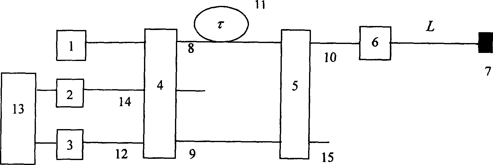
[0067] Embodiment 1. In this embodiment, the laser used is the SO3-B type superluminescent diode (SLD) type stable light source (1) produced by the 44 Research Institute of the Electronics Group Corporation. The fiber optic coupler is a single-mode fiber optic coupler produced by Wuhan Institute of Posts and Telecommunications. The photodetectors (2) and (3) are InGaAs photodetectors produced by 44, whose model is GT322C500. The optical fiber used is a G652 single-mode optical fiber produced by Corning in the United States. The jumper is FC / PC single-mode fiber jumper produced by Wuhan Institute of Posts and Telecommunications. The optical feedback device (7) is an aluminum film evaporated at the end of the optical fiber, and the reflectivity is greater than 95%.

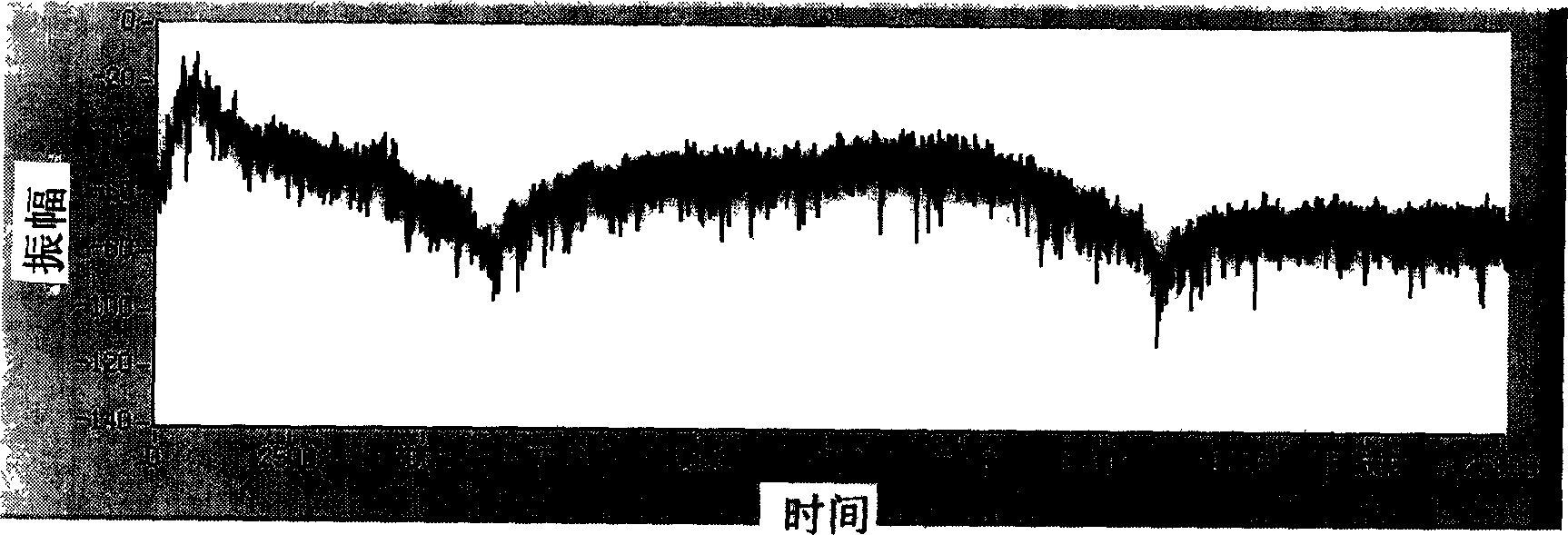
[0068] In the embodiment, the distance L between the position of the disturbance source in the sensing fiber and the reflection end of the fiber is 8158 meters, and the spectrum defect situation in the embodiment ...


PUM

PropertyMeasurementUnit
Wavelengthaaaaaaaaaa

Abstract

This invention relates to a new fiber position monitoring method and its system. The system is characterized by the following: it uses single light fiber as large arrange distribution sensor fiber and gets the disturbing source physical characteristics according to the phase inversion of the interference signals and determines the detail positions of disturbing source according to the frequency spectrum of the interference signals. It uses the sensor fiber end and reflecting lens method to improves the system accuracy.

Description

technical field [0001] The invention is a new optical fiber positioning monitoring method and an all optical fiber positioning monitoring system constructed according to the method. Background technique [0002] Maintaining the security of infrastructure is a basic requirement for social stability and rapid economic development. Safety monitoring of infrastructure such as communication optical cables (including submarine optical cables), high-voltage power grids, oil pipelines, and gas pipelines is not only a guarantee for the technical functions of these facilities, but also an effective means to avoid major economic losses and maintain social stability and development. . Especially with the rapid development of infrastructure construction, it presents new characteristics of wide geographical distribution, high complexity, and further increasing importance, which increases the scope and frequency of infrastructure damage, and the difficulty of safety monitoring, The impor...

Claims


Application Information

Patent Timeline
IPC IPC(8): G01D5/353G02B6/00
Inventor 贾波张天照唐璜章骅吴东方
Owner FUDAN UNIV
Why Eureka
Try Eureka