Connecting structure for rod

A technology of connecting structure and ground connection, which can be used in the connection of rods, connecting members, cleaning carpets, etc., and can solve problems such as gaps

Inactive Publication Date: 2005-07-13
KAO CORP +1
View PDF2 Cites 11 Cited by
  • Summary
  • Abstract
  • Description
  • Claims
  • Application Information

AI Technical Summary

Problems solved by technology

[0004] (1) Although the first rod and the second rod maintain the connected state by fitting and fixing their coupling protrusions and coupling holes, there will inevitably be a gap between the protrusions and the holes as the fitting relationship

Method used


Image

  • Connecting structure for rod
  • Connecting structure for rod
  • Connecting structure for rod

Examples


Embodiment approach 1

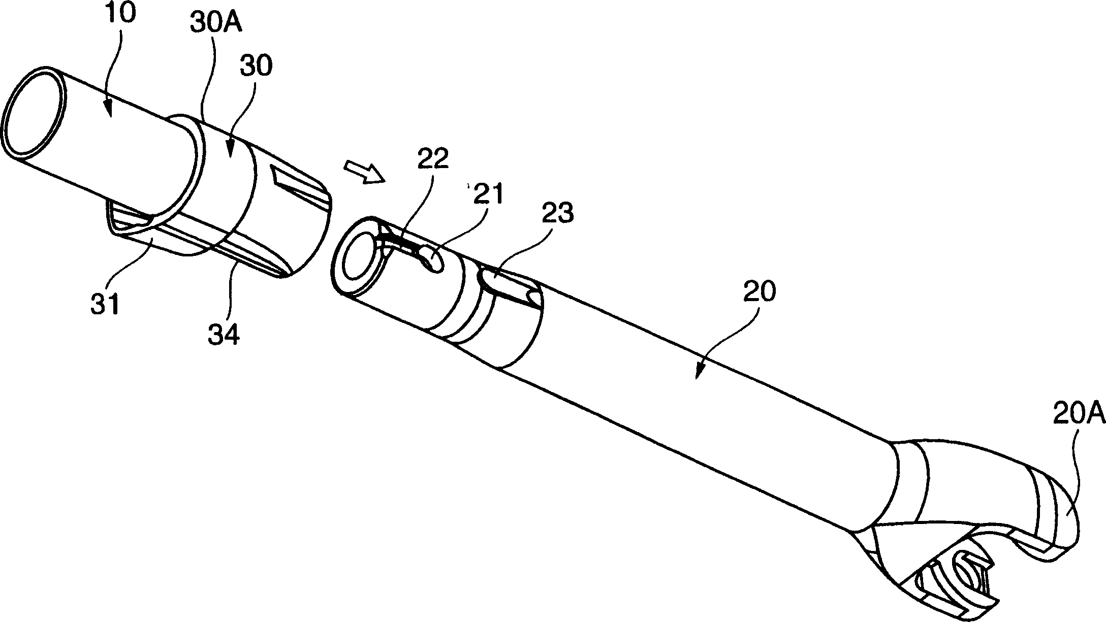
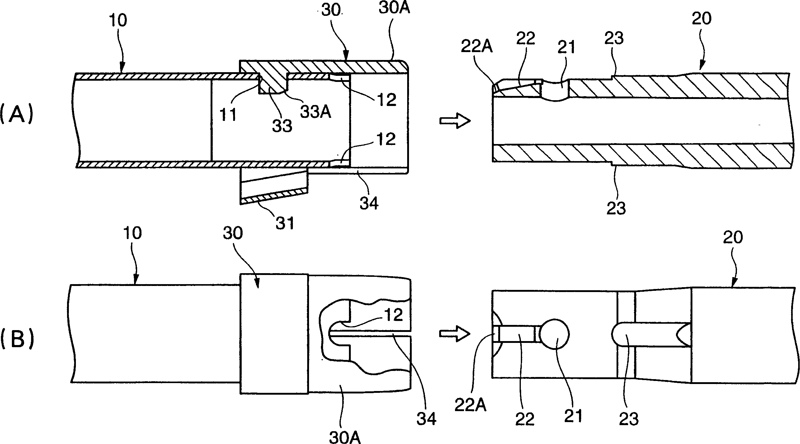
[0019] figure 1 It shows that the first rod 10 and the second rod 20 constituting a part of the handle of the cleaning tool are inserted into each other and connected male and female by the connecting tool 30 provided on the first rod 10 . Moreover, the 2nd lever 20 is equipped with 20 A of cleaning head attachment parts as a front-end|tip part which comprises a handle.

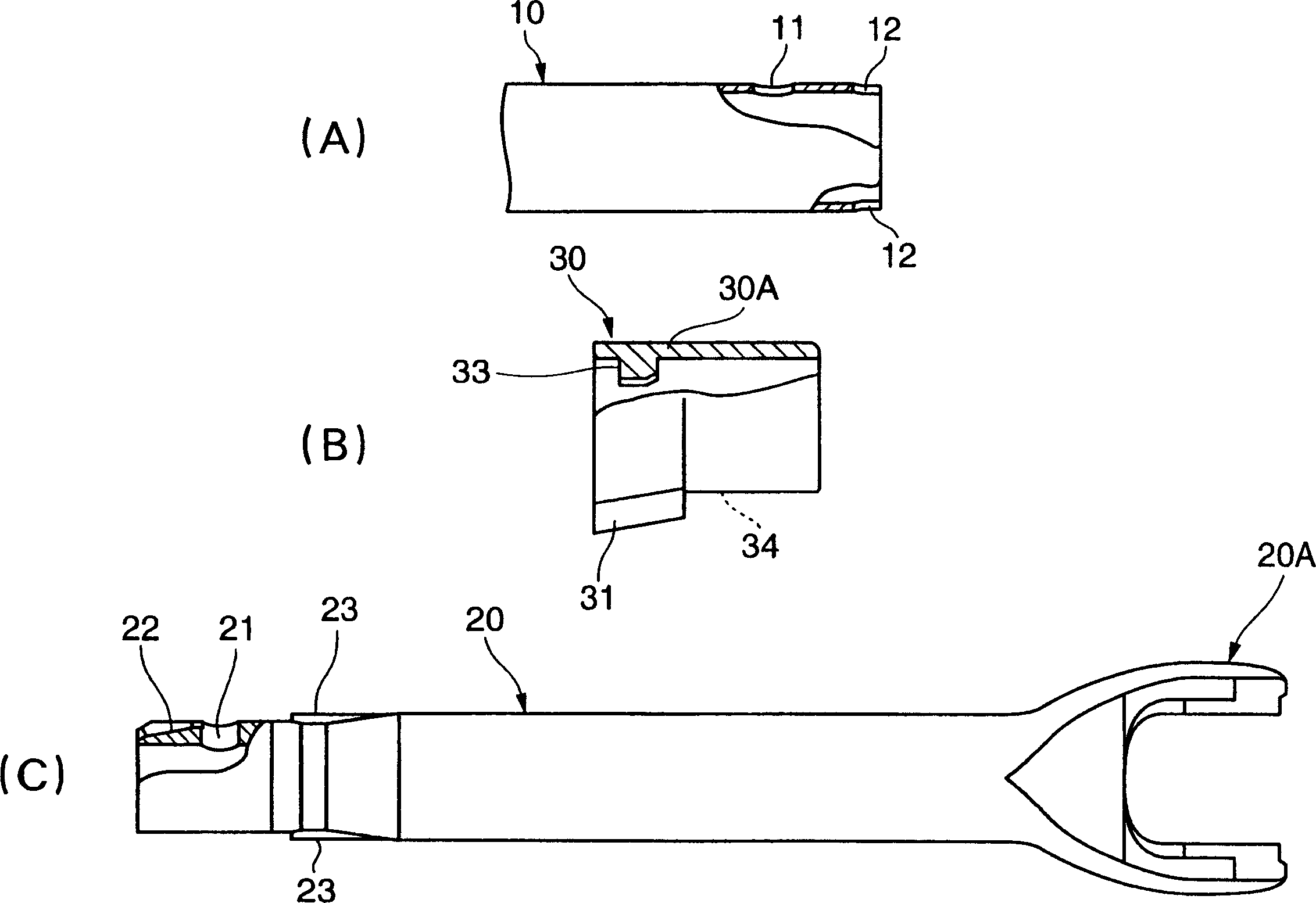
[0020] The first rod 10 is made of pipe material, such as figure 2 As shown in A, on the peripheral wall of one end of the pipe material, there are mounting holes 11 for connecting the tool 30 penetratingly. Two positions at 100° intervals, or a single position) is provided with a notch 12 for anti-rotation. The anti-rotation notch 12 is formed in a U-shape opening outward in the axial direction.

[0021] The connecting tool 30 installed on the first bar 10, such as figure 2 As shown in (B), it is substantially linear in its entirety (straight portion 30A), and is constituted by a short cylindrical memb...

Embodiment 2

[0037] Figure 8 It shows that the first rod 110 and the second rod 120 constituting a part of the handle of the cleaning tool are inserted into each other through the connecting tool 130 attached to the first rod 110, and the male and female are fitted and connected.

[0038] The first rod 110 is made of a pipe, and has an annular mounting groove 111A and a mounting hole 111B for connecting the tool 130 on the peripheral wall of one end of the pipe. Strip-shaped anti-rotation ribs 112 .

[0039] The connecting tool 130 mounted on the first rod 110 is composed of a C-shaped fixing ring 131 and an arc-shaped operating ring 132, wherein the fixing ring 131 is formed at a half circumference larger than the mounting groove 111A of the first rod 110. Within the range, the operating ring 132 is coupled to both ends of the fixing ring 131 by pins so that it can be embraced almost without gap by the habit of ejecting the reduced diameter. In the state where the connection tool 130 i...


PUM


Abstract

A rod connection structure that connects a first rod (10) and a second rod (20) in a male-female fit, and an anti-rotation device is provided on any one of the first rod (10) and the second rod (20). Rib (23), anti-rotation notch (12) is provided with on the other, while the coupling protrusion (33) of the 1st bar (10) is fitted and fixed in the coupling hole 21 of the 2nd bar (20), the two The anti-rotation ribs (23) and the anti-rotation notches (12) of the rods (10, 20) can be combined with each other at least in the circumferential direction of the two rods (10, 20).

Description

technical field [0001] The invention relates to a connection structure of rods. Background technique [0002] As the connection structure of the rods such as the handle of the cleaning tool and the handle of the cane, as described in JP-A-2001-317513 (Patent Document 1) and JP-A-2003-102664 (Patent Document 2), the male and female connections are connected In the case of the first rod and the second rod, a coupling protrusion that pops out in the radial direction of the first rod is provided on the peripheral surface of the first rod, and at the same time, a coupling that fits and fixes the first rod is provided on the peripheral surface of the second rod The joint hole of the protrusion, and the guide groove extending from the front end edge to the joint hole for guiding the joint protrusion. The connecting protrusion of the first rod is guided while being pressed by the guide groove of the second rod, and is fitted and fixed to the coupling hole of the second rod so as to...

Claims


Application Information

Patent Timeline
Patent Type & Authority Applications(China)
IPC IPC(8): A47L13/20F16B7/00F16B7/20
Inventor 加藤诚富冈和幸
Owner KAO CORP
Why Eureka
Try Eureka