Electrochromism display device

A technology for electrochromic and display devices, applied in instruments, nonlinear optics, optics, etc., can solve the problems of low electrochromic efficiency and achieve the effect of high electrochromic efficiency

Inactive Publication Date: 2005-07-20
HONG FU JIN PRECISION IND (SHENZHEN) CO LTD +1
View PDF2 Cites 9 Cited by
  • Summary
  • Abstract
  • Description
  • Claims
  • Application Information

AI Technical Summary

Problems solved by technology

[0007] In order to overcome the deficiency of the low electrochromic efficiency of the electrochromic display device

Method used


Image

  • Electrochromism display device
  • Electrochromism display device
  • Electrochromism display device

Examples


Embodiment Construction

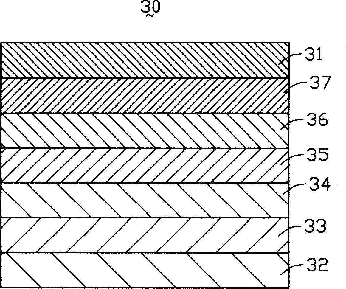
[0013] see image 3 , is a schematic diagram of the structure of the electrochromic display device of the present invention. The electrochromic display device 30 includes an upper substrate 31, a lower substrate 32, a lower electrode layer 33, an ion storage layer 34, an electrolyte layer 35, an electrochromic Variable layer 36 and upper electrode layer 37. The electrochromic display device 30 is driven by an external voltage source (not shown in the figure), and the external voltage source is connected to the upper electrode layer 37 and the lower electrode layer 33 respectively.

[0014] At least one of the upper substrate 31 and the lower substrate 32 is a transparent glass substrate as an image display plane. The lower electrode layer 33 and the upper electrode layer 37 are transparent Indium Tin Oxide (ITO) thin films, which serve as the counter electrode and the display electrode of the electrochromic display device 30 respectively. The indium tin oxide thin film is f...


PUM


Abstract

This is a kind of electro-color-change display device including a upper basal board, a nether basal board, a outer voltage source, a nether electrode layer equipped orderly from nether to upper, a ion storage layer, a electrolyte layer, a electro-color-change layer and a upper electrode layer. The outer voltage source are respectively connected with the upper electrode and the nether electrode layer. The electro-color-change layer is a porous membrane, which presents a nanometer crystal form and clings to the upper electrode layer.

Description

【Technical field】 [0001] The invention relates to a display device, in particular to an electrochromic display device. 【Background technique】 [0002] Usually, the change of color can be realized by using a color-changing material, and the color-changing material produces a color change by absorbing external energy, such as light, electricity or heat. According to the principle of discoloration, discoloration materials can be divided into electrochromic materials, thermochromic materials and photochromic materials. In contrast, since photochromic or thermochromic materials and corresponding device systems are easily affected by environmental or non-human factors, electrochromic materials and system devices using them are easier to control than the other two. At the same time, electrochromic materials have a large adjustable wavelength range and optical density difference, which can block most heat sources and visible light wavelengths. Therefore, electrochromic materials a...

Claims


Application Information

Patent Timeline
IPC IPC(8): G02F1/15
Inventor 陈杰良
Owner HONG FU JIN PRECISION IND (SHENZHEN) CO LTD
Why Eureka
Try Eureka