Valve arrangement for reciprocating machinery such as a pump and a compressor

A reciprocating and valve device technology, which is applied to parts of pumping devices for elastic fluids, valve devices, liquid variable capacity machines, etc., can solve the problem of skewing, uneven wear, and disassembly of valve bodies and valve seats. open and replace

Inactive Publication Date: 2005-07-20
NAT OILWELL NORWAY
View PDF0 Cites 10 Cited by
  • Summary
  • Abstract
  • Description
  • Claims
  • Application Information

AI Technical Summary

Problems solved by technology

The result is that the valve body and seat are skewed or worn unevenly, which causes the valve to leak when closed, in which case the valve must be replaced or the valve must be disassembled and the worn part replaced

Method used


Image

  • Valve arrangement for reciprocating machinery such as a pump and a compressor
  • Valve arrangement for reciprocating machinery such as a pump and a compressor
  • Valve arrangement for reciprocating machinery such as a pump and a compressor

Examples


Embodiment Construction

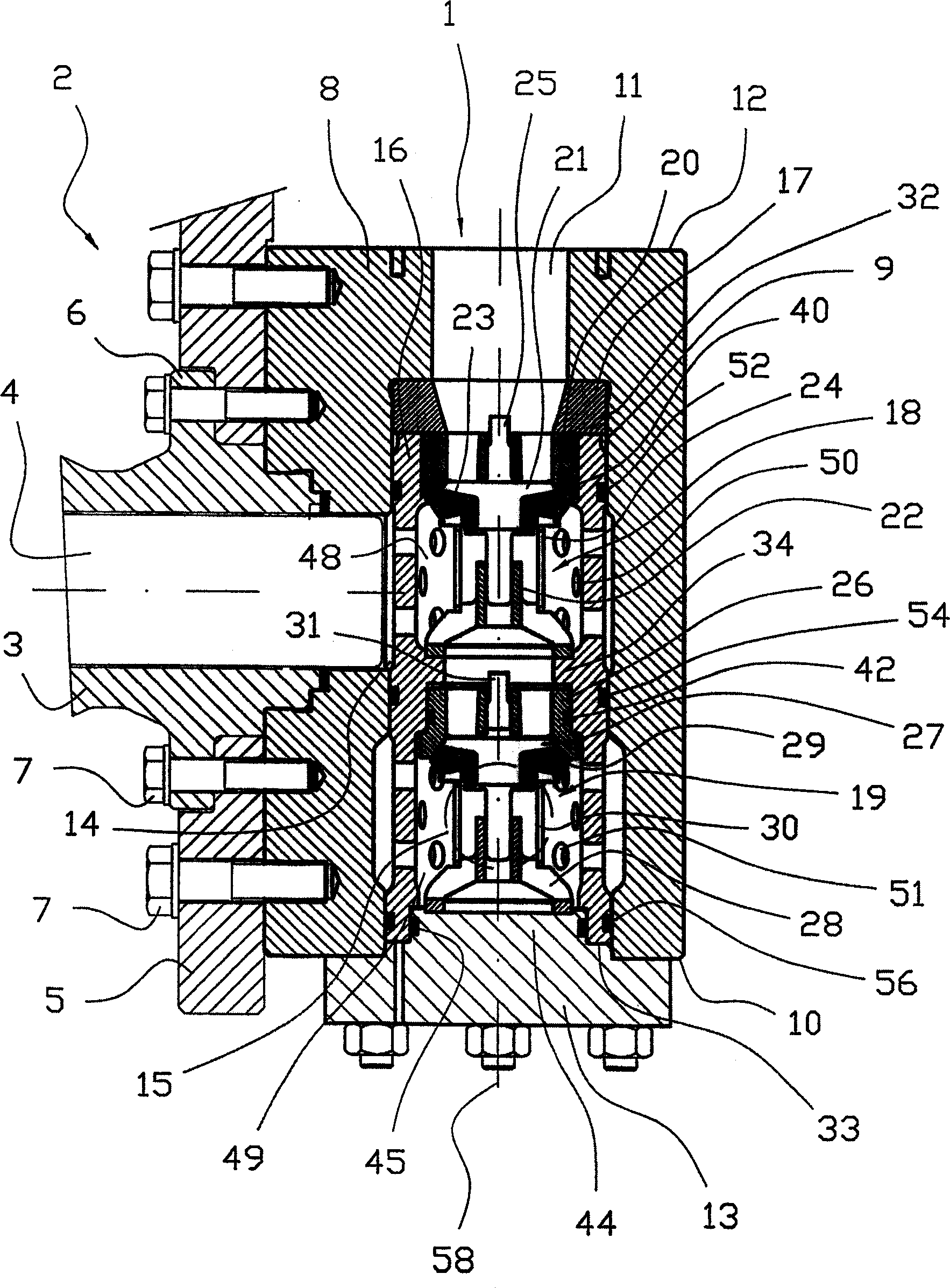
[0025] exist figure 1 In, reference 1 denotes the valve arrangement installed on the piston pump 2, and this valve arrangement is connected on the cylinder 3 of the piston pump, wherein a reciprocating piston 4 is installed in a known manner. A mounting plate 5 forms an extension of a flange 6 on the cylinder 3 . Both the mounting plate 5 and the valve device 1 are connected to the flange 6 and thus to the cylinder 3 by using a screw 7 .

[0026] The valve device 1 comprises a housing 8, wherein a bore 9 opening at one end 10 of the housing 8 terminates in the housing 8 and is connected to an outlet 11 opening at the other end, i.e. the opposite end, of the housing 8. connected. A cover 13 is designed to cover the hole 9 at the first end 10 of the housing 8 .

[0027] The working channel 14 in the housing 8 forms an extension of the cylinder 3 so as to communicate the cylinder with the bore 9 . An outlet 15 drawn out of the housing 8 from the hole is figure 1 Indicated by...


PUM


Abstract

A valve arrangement for reciprocating machine, where the arrangement (1) comprises an in-valve (18) and an out-valve (19), each valve (18), (19) being a springloaded one-way valve designed to open for flow when the pressure differential in the direction of flow provides a force that exceeds the spring tension, wherein the valves (18, 19) are mounted in a casing (8) that forms or is connected to the cylinder head of the reciprocating engine (2). The in-valve (18) and the out-valve (19) are mounted in a sleeve (16) designed to be fitted in a bore (9) in the casing (8), and where fluid may flow to the sleeve (16) from an inlet (11) in the casing (8) and into the sleeve (16) via the in-valve (18), and where the sleeve (16) is provided with at least one perforated area where fluid may flow radially out of or into the sleeve (16) via holes (50, 51), thereby flowing to or from a passage (14, 15) that forms a perpendicular or near perpendicular connection with the bore (9).

Description

technical field [0001] The present invention relates to a valve arrangement for reciprocating machines such as pumps and compressors. Background technique [0002] A typical reciprocating machine or reciprocating engine has an induction valve and an exhaust valve for each piston, hereinafter referred to as the in-valve and out-valve . Typically, spring-loaded check valves are used, where a spring closes the valve by pressing the valve body against the valve seat. By acting a mechanical action on the valve body or by acting on the valve body the pressure of the working medium of the reciprocating engine, creating a force opposite to said spring force, the valve is opened to allow flow, the working The medium is hereinafter referred to as fluid. [0003] If a valve of this type is arranged such that the direction of flow through the valve is parallel to the cylinder axis of the reciprocating engine, the valve and accompanying piping will protrude a relatively long distance ...

Claims


Application Information

Patent Timeline
Patent Type & Authority Applications(China)
IPC IPC(8): F04B53/10F16K15/06
CPCF04B53/109Y10T137/7559Y10T137/7838F16K15/066
Inventor 马格纳·穆厄奥厄·许林斯塔德
Owner NAT OILWELL NORWAY
Why Eureka
Try Eureka