Wheel rim squeezing formation for spinning flat pulley

An extrusion forming and flat pulley technology, which is applied in the field of flat pulley processing technology, can solve the problems that flat pulleys are not easy, affect normal use, cannot achieve smooth surface, etc., and achieve the effect of satisfying appearance requirements.

Inactive Publication Date: 2005-07-27
常州市棱光轴承有限公司
View PDF0 Cites 6 Cited by
  • Summary
  • Abstract
  • Description
  • Claims
  • Application Information

AI Technical Summary

Problems solved by technology

However, in the middle of the working surface of the rim of the flat pulley processed in this way, there will be a circle of grooves left by the metal cut by the mold knife, which not only affects the appearance of the product, but a

Method used


Image

  • Wheel rim squeezing formation for spinning flat pulley
  • Wheel rim squeezing formation for spinning flat pulley

Examples


Embodiment Construction

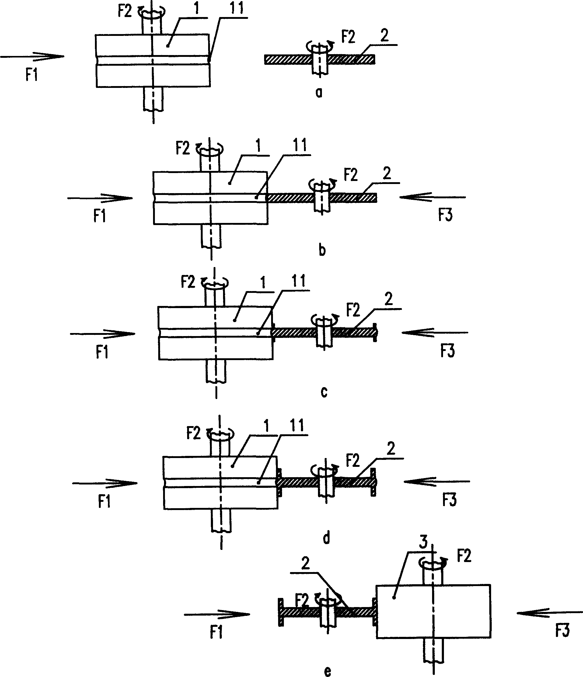
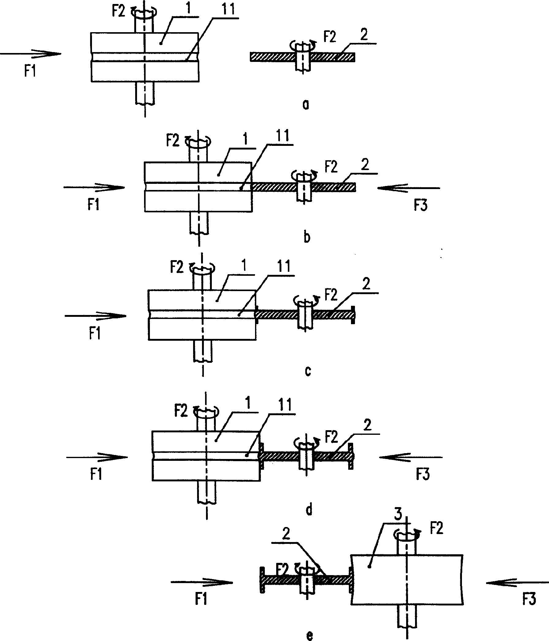
[0010] Such as figure 1 The first embodiment of the spinning flat pulley rim extrusion forming process shown in the present invention has the following steps: A. initial forming, such as figure 1 a. figure 1 b. figure 1 c. figure 1 As shown in d, the metal plate 2 and the forming die 1 with a bow-shaped groove 11 are respectively fixedly installed on the two rotating shafts of the machine tool, the machine tool starts to work, the metal plate 2 and the forming die 1 rotate in opposite directions, and the forming die is pushed 1. Make the forming die 1 move towards the metal plate 2, and the metal plate 2 pushes to the bottom of the bow-shaped groove 11. The metal plate 2 is subjected to the rotational force F2, and at the same time, the metal plate 2 is also subjected to the pressure F1 of the forming die 1, and generates a reaction force F3 , the metal plate 2 is under the action of F1, F2, F3, the metal on the edge of the metal plate 2 flows to both sides evenly along the...


PUM


Abstract

A spinning-pressing technology for forming the rim of belt wheel includes such steps as providing a forming die with bow-shaped slot, pushing a metal plate to the bottom of said slot, pressing the metal plate while squeezing it by said die to make it be uniformly deformed in the slot to become a wheel rim, and further shaping. Its advantage is smooth surface.

Description

technical field [0001] The invention relates to the technical field of flat pulley processing technology, in particular to a spinning flat pulley rim extrusion forming process. Background technique [0002] The flat belt wheel used for flat belt transmission consists of three parts: rim, spoke and hub. The working surface of the rim and the flat belt should be smooth, and the surface is rough generally Ra=3.2um to reduce the wear of the belt. In order to prevent the belt from falling off, some pulleys have a convex surface. In the spinning forming of flat pulleys, the forming of the rim is the most critical and the most difficult. On the cross-section of the flat pulley, the rim and the spokes are vertical and symmetrically distributed around the centerline of the spokes. To make the sheet into this shape, a special mold knife is often used to cut the end face of the sheet into two halves, and extend them in two opposite directions to form a rim. However, in the middle of...

Claims


Application Information

Patent Timeline
IPC IPC(8): B21C23/03
Inventor 蒋新
Owner 常州市棱光轴承有限公司
Why Eureka
Try Eureka