Line thermal head and thermal-transfer line printer

A technology of thermal head and printer, which is applied in printing and other directions, can solve the problems of reduced printing quality, high noise, and high wrinkle of ink ribbon 105, and achieve the effects of improving movement stability, improving printing quality, and uniform peeling distance

Inactive Publication Date: 2005-07-27
ALPS ALPINE CO LTD
View PDF1 Cites 6 Cited by
  • Summary
  • Abstract
  • Description
  • Claims
  • Application Information

AI Technical Summary

Problems solved by technology

For example, since the peeling distance L is different between the end portion 108e and the central portion 108c of the peeling metal plate, a positional difference occurs in the peeling time, and as a result, the print quality is reduced and the noise is too large due to peeling. question
However, if the shape of the peeling metal plate 108 is formed parallel to the arrangement direction of the heating element 103h, the optimum tension cannot be given to the ink ribbon 105, and as a result, it is impossible to solve the problem that occurred before the peeling metal plate was bent. The "slack" and "wrinkle" problem spots
[0017] In addition, it is known that the uneven tension in the width direction of the ink ribbon 105 is generated because of the deformation of the longitudinal central portion of the ribbon shaft for moving the ink ribbon 105 or the guide shaft that restricts the moving path of the ink ribbon 105. The axis is arranged on the downstream side of the moving direction of the ink ribbon 105 from the line thermal head 103 or the peeling metal plate 108, especially when the tension of the ink ribbon 105 is large, the ink ribbon passing through the line thermal head 103 The tension tends to be weak at the center in the width direction and strong at both ends, and there is a high possibility of wrinkling on the ink ribbon 105.

Method used


Image

  • Line thermal head and thermal-transfer line printer
  • Line thermal head and thermal-transfer line printer
  • Line thermal head and thermal-transfer line printer

Examples


Embodiment Construction

[0051] Hereinafter, the present invention will be described by means of embodiments shown in the drawings.

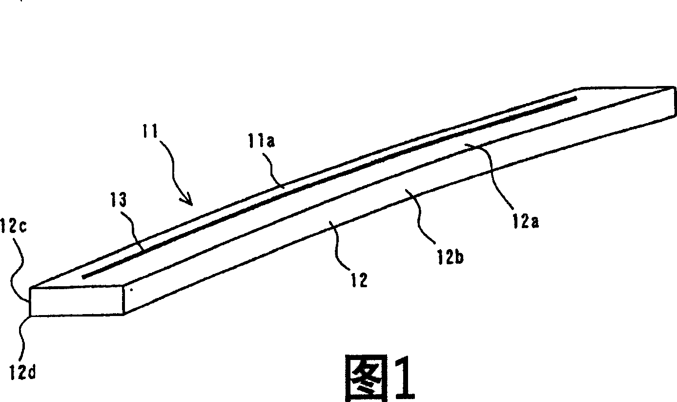
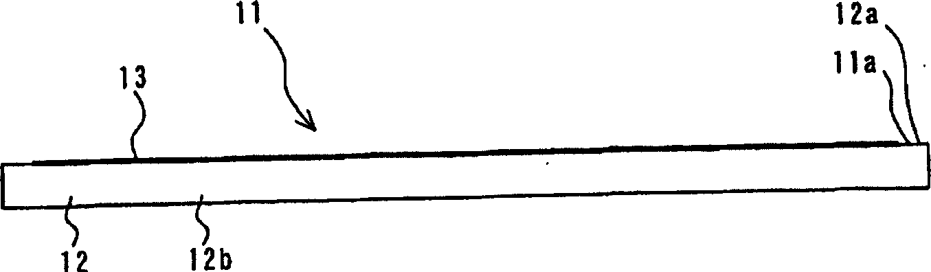
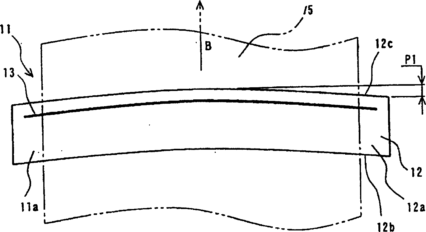
[0052] Figure 1 to Figure 4 It is a schematic diagram of the main part of the first embodiment of the line thermal head involved in the present invention, and Fig. 1 is a perspective view, figure 2 is the front view of Figure 1, image 3 Yes figure 2 floor plan, Figure 4 Yes figure 2 right side view of .

[0053] Figure 1 to Figure 4 As shown, the line thermal head 11 of this embodiment has a substrate 12 substantially formed in a flat plate shape and a image 3 A plurality of heat generating elements 13 of the ink of the ink ribbon 15 shown in phantom lines. Then, a plurality of heating elements 13 are arranged on the upper surface 12 a of the substrate 12 , and the upper surface 12 a of the substrate 12 on which the plurality of heating elements 13 are arranged becomes the printing surface 11 a of the line thermal head 11 .

[0054] The above substrate 1...


PUM


Abstract

In order to improve the traveling stability of an ink ribbon, a thermal head having a structure in which an edge of one surface of a substrate, lying downstream with respect to the traveling direction of an ink ribbon, is formed so as to have a curved shape projecting most downstream with respect to the traveling direction of the ink ribbon at the widthwise central portion of the ink ribbon or a thermal-transfer line printer having a structure in which a separation member separating the ink ribbon from a paper sheet and a tension-exerting section are independently formed from each other is provided.

Description

technical field [0001] The present invention relates to a thermal line head and a thermal transfer printer suitable for improving the movement stability of an ink ribbon. Background technique [0002] Existing known thermal transfer line printers, through the wide ink ribbons such as ink film and ink plate and the format paper as the recording medium, the line format with the length corresponding to the vertical or horizontal printing range of the format paper is made The thermal head is docked with the platen, and in this docked state, while conveying the ink ribbon and the format paper, based on the printing information (recording information), selectively drive the printers arranged in the longitudinal direction of the line thermal head. Printing (recording) is performed by duplicating the ink of the ink ribbon on the form by printing a plurality of heating elements with a width (recording width) and heating them. [0003] Below, refer to Figure 19 to Figure 21 , to des...

Claims


Application Information

Patent Timeline
Patent Type & Authority Applications(China)
IPC IPC(8): B41J2/335
CPCB41J2/335
Inventor 寺尾博年和宇庆知子星野久佐佐木恒之丸山贵史
Owner ALPS ALPINE CO LTD
Why Eureka
Try Eureka