Cleaning device for textile machines

A cleaning device and textile machinery technology, which is applied in textiles, textiles, papermaking, and auxiliary equipment for weaving. It can solve the problems of high cost and poor cleaning effect, and achieve the effect of reducing the height of the structure.

Inactive Publication Date: 2005-07-27
SOHLER NEUENHAUSER
View PDF1 Cites 14 Cited by
  • Summary
  • Abstract
  • Description
  • Claims
  • Application Information

AI Technical Summary

Problems solved by technology

Although the cleaning effect of this solution

Method used


Image

  • Cleaning device for textile machines
  • Cleaning device for textile machines
  • Cleaning device for textile machines

Examples


Embodiment Construction

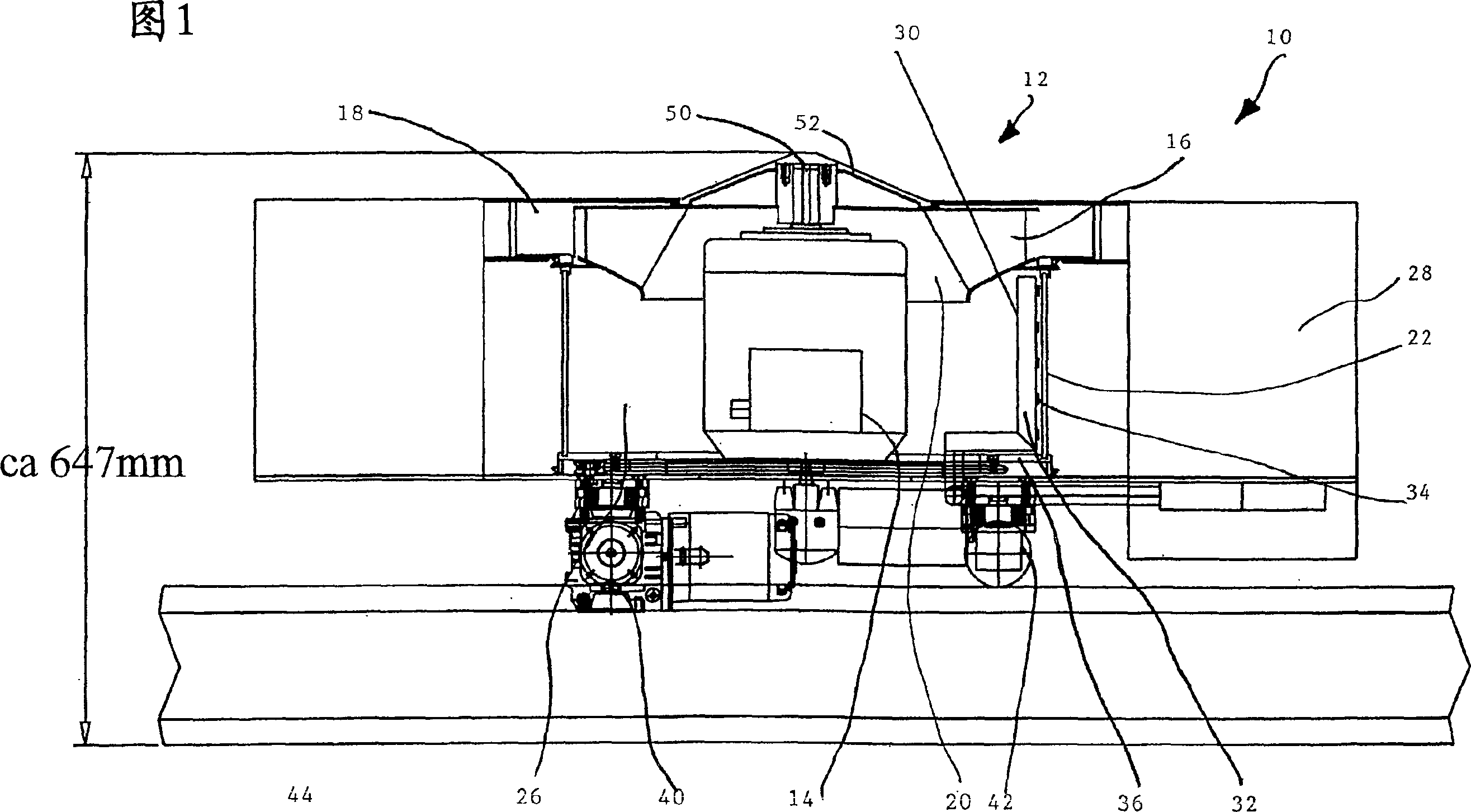
[0031] The cleaning device 10 shown in FIG. 1 comprises a trash remover 12 with a trash remover motor 14 which drives a trash remover wheel 16 . In known manner, a radial trash remover is provided. The trash trap is arranged in a known manner in a trash trap housing 18 . An axial inflow parallel to the motor is achieved by means of the axially oriented trash filter intake opening 20 , which has the effect of cooling the trash filter motor 14 in the cooling air flow.

[0032] The electric machine is surrounded by an annular filter 22 according to the invention almost over its entire height—in the exemplary embodiment shown approximately over 80% of its height. The diameter of the ring filter 22 is about 3 times the diameter of the motor in order to obtain sufficient internal free space for forming the suction chamber. The suction chamber 26 communicates in a known manner with the suction channel of the textile machine cleaning device, while a blowing chamber 28 also communica...


PUM


Abstract

The assembly to clean a textile machine, and especially a loom, has a blower (12) with a motor to drive a fan wheel. The fan draws air from a suction zone with a number of suction channels. The assembly also has a filter in the suction zone, which extends ringwise basically and pumps the air from the exterior to the interior. A rotating ring filter (22) can support rotationally. The filter is cleaned by compressed air blown out from the interior of the filter.

Description

technical field [0001] The invention relates to a cleaning device according to the preamble of claim 1 . Background technique [0002] It is known that textile machines must simultaneously be cleaned of impurities during the continuous formation of the slivers in order to ensure trouble-free operation. For this purpose, the cleaning device of the textile machine is usually mounted on guide rails and moved along the textile machine. The cleaning of the textile machine is carried out through a blowing pipe with a corresponding blowing port and a suction pipe with a corresponding suction port, and a suction airflow and a blowing airflow are generated by a (blowing) decontamination device arranged in the cleaning device. Its basic principles are proven to be reliable and widely adopted. [0003] In order to separate the formed strands from the suction air and to clean the blowing air, filter devices are usually provided. A disadvantage of such a filter device is that, as the ...

Claims


Application Information

Patent Timeline
IPC IPC(8): D01H11/00D03J1/00
CPCD01H11/005D03J1/002
Inventor 马克·佐勒伊杜尔德·沃恩德尔
Owner SOHLER NEUENHAUSER
Why Eureka
Try Eureka