Driving device

A technology of driving device and transmission device, applied in the direction of transmission device, cam follower, textile, etc., can solve the problems of position uncertainty, occupying a lot of space, unfavorable accumulation and removal of harmful substances, etc., to save costs and reduce inertia and the effect of energy consumption

Inactive Publication Date: 2011-02-23
N V MICHEL VAN DE WIELE
View PDF0 Cites 0 Cited by
  • Summary
  • Abstract
  • Description
  • Claims
  • Application Information

AI Technical Summary

Problems solved by technology

Due to the above reasons, the device needs to occupy a lot of space, which is not conducive to the removal of harmful accumulations and causes location uncertainty

Method used


Image

  • Driving device
  • Driving device
  • Driving device

Examples


Embodiment Construction

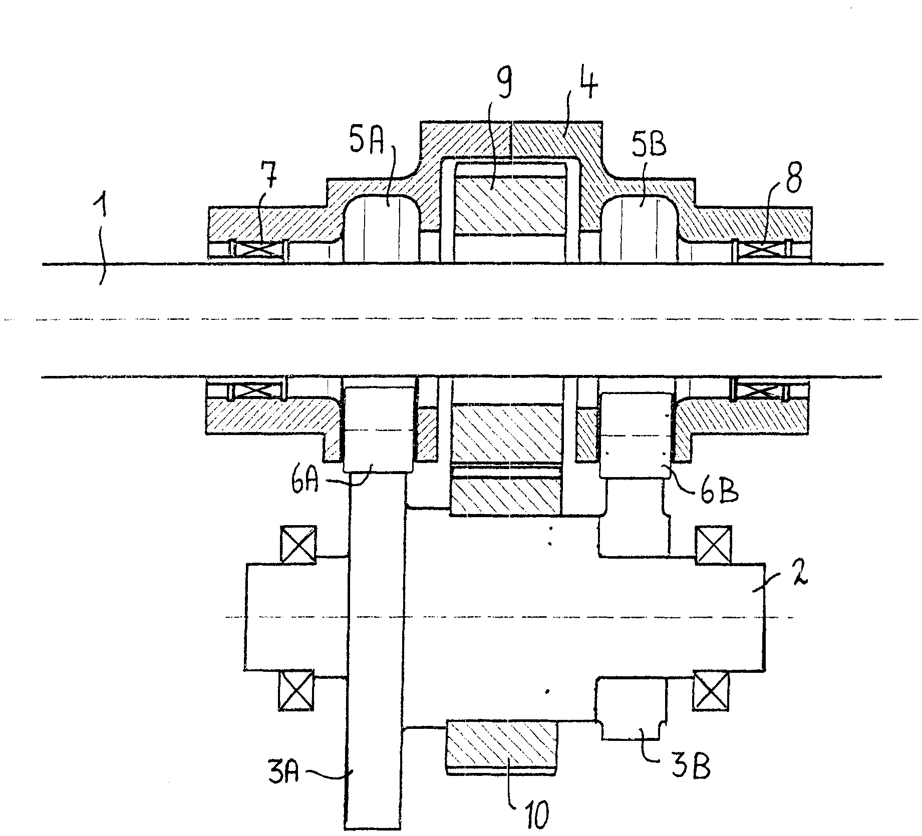
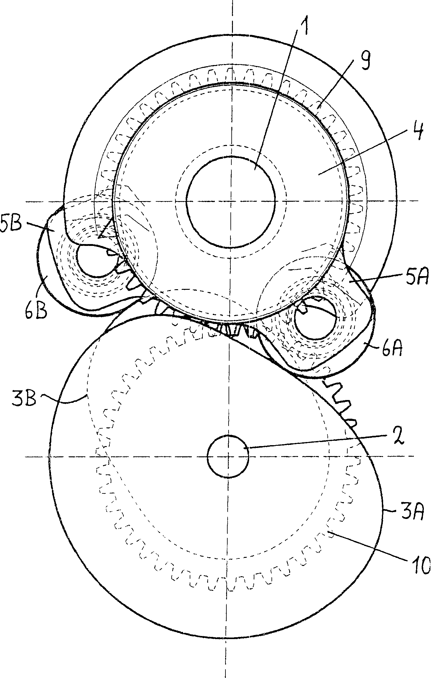
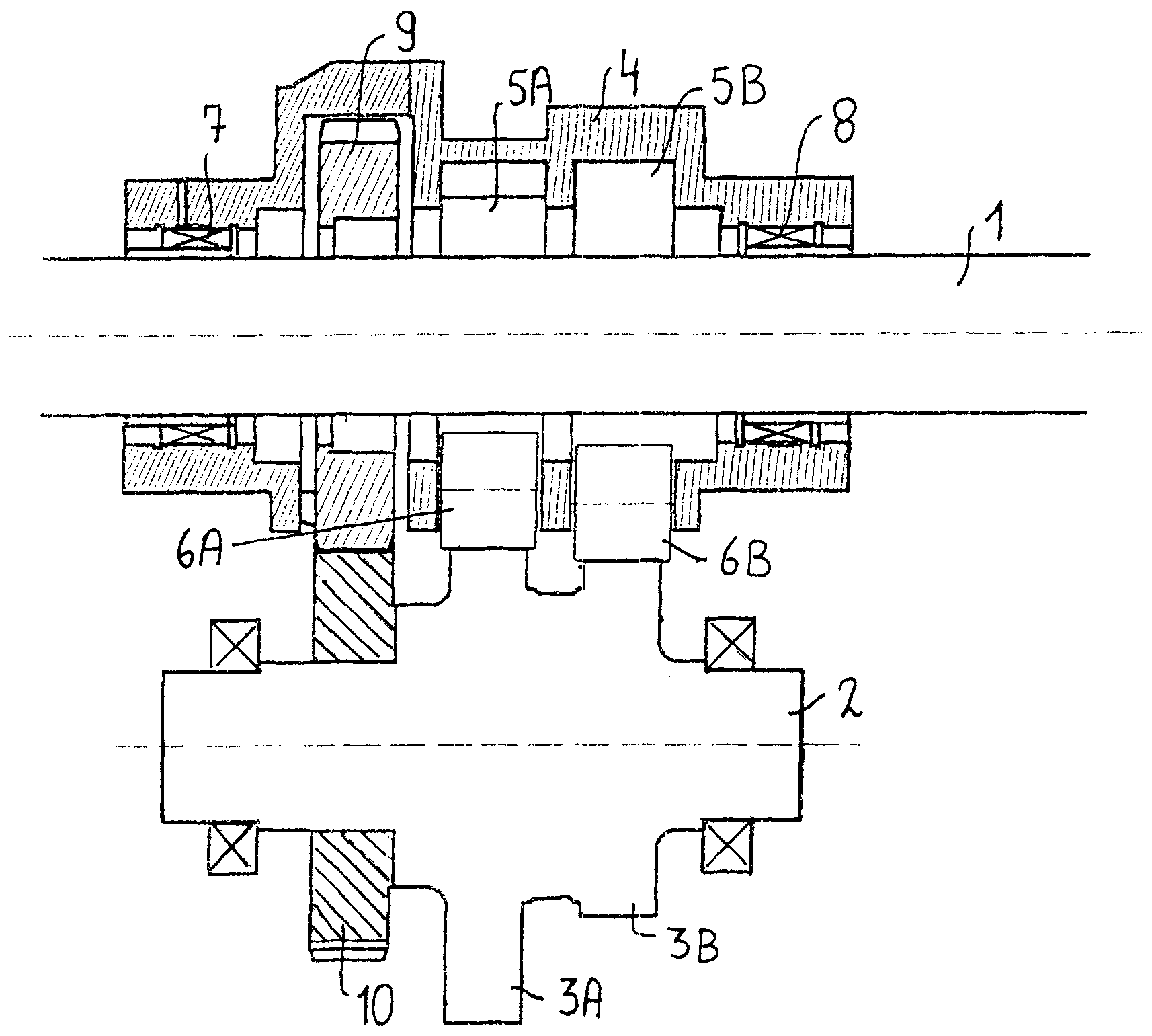
[0035] figure 1 with figure 2 A sectional view and a side view of a first embodiment of the invention are shown, the drive device comprising a drive shaft 1 and a cam shaft 2 . The drive shaft 1 and the cam shaft 2 are arranged with meshing gears 9, 10, respectively. Two conjugate cam disks 3A, 3B are respectively arranged on both sides of the gear wheel 10 on the camshaft 2 .

[0036] Arranged on the drive shaft 1 is a cam follower 4 , which is supported coaxially on the drive shaft 1 via two bearings 7 , 8 . Bearings 7 , 8 are located on the drive shaft 1 and are arranged on both sides of the gear 9 . The cam follower lever 4 has two first lever arms 5A, 5B, and transmission rollers 6A, 6B are respectively arranged at the ends of the first lever arms 5A, 5B. When the cam discs 3A, 3B rotate, the designed transmission The rollers 6A, 6B move along the periphery of a corresponding cam plate 3A, 3B, so that the cam follower 4 is repeatedly rotated. In addition, the cam f...


PUM


Abstract

The present invention relates to a driving device, comprising at least one body which may be put in an alternating rotary motion by the rotation of at least one cam; the said body being provided to be rotatable on a shaft, which itself is provided to perform a continuous rotary motion. The said body may be mounted on bearings on the drive shaft or on a shaft that may be driven by the drive shaft.Because of the continuous rotation of the said shaft, the bearings of this body will be subjected to a uniform load along their circumference and consequently will be likewise subjected to a uniform wear. This will enhance the life span of the bearing. Because of which the driving device will operate more precisely and it may be carried out in a more compact form. This invention likewise relates to a machine provided with such a driving device, more particularly to a textile machine.

Description

technical field [0001] The invention relates to a driving device comprising at least one base body which is repeatedly rotated by the rotation of at least one cam. [0002] More specifically, the invention relates to an actuation device of which said base is designed to actuate an element driven by repeated rotation of the base. The movement of the driven element can be any form of movement, for example reciprocating or swinging along a straight line or a curve, or a combination or continuation of different forms of movement. [0003] Furthermore, the invention relates to a machine comprising a drive device according to the invention, and more particularly to a machine in which a base body of the machine is at least reciprocating by rotation of at least one cam to A component connected to the base is driven. More specifically, the invention relates to a textile machine, such as a weaving machine or a jacquard machine or a weaving machine. Background technique [0004] Tex...

Claims


Application Information

Patent Timeline
Patent Type & Authority Patents(China)
IPC IPC(8): F16H37/12D03C5/02D03D49/30D03D47/27D03D49/60D04B27/08F16H25/16F16H53/06
CPCF16H25/16D03D47/27D03D49/60D03C5/02D04B27/08D03D47/271F16H53/06D03D47/275Y10T74/1836Y02P70/62
Inventor 乔尼·德比斯费迪·德耶格尔
Owner N V MICHEL VAN DE WIELE
Why Eureka
Try Eureka