Predicting method for system lock in pattern coordinate design

A collaborative design system and prediction method technology, applied in the direction of program control devices, multi-program devices, etc., can solve problems such as the impossibility of predicting user intentions, and achieve the effects of conflict prevention, good practicability, and reduced waste of design time

Inactive Publication Date: 2005-07-27
ZHEJIANG UNIV
View PDF0 Cites 5 Cited by
  • Summary
  • Abstract
  • Description
  • Claims
  • Application Information

AI Technical Summary

Problems solved by technology

While traditional locking methods are impossible to predict user intent

Method used


Image

  • Predicting method for system lock in pattern coordinate design
  • Predicting method for system lock in pattern coordinate design
  • Predicting method for system lock in pattern coordinate design

Examples


Embodiment Construction

[0039] The lock mechanism is widely used when implementing the internet-based distributed pattern collaborative design technology.

[0040] The method involves related symbol interpretation:

[0041] Forec L S Uk: The owner of the system predictive lock.

[0042] Forec L S Uk orientation : The system predicts the direction of the lock to be locked.

[0043] Forec L S Uk renion : The system predicts the area to be locked.

[0044] ForecCoEdL S Uk region : Regions that compete with each other for lock after the system predicts a conflict.

[0045] ForecEdL S Uk region : The system predicts the final locked region after conflict resolution.

[0046] L u Ux region : A region that has been locked by a user.

[0047] L u Ux time : The time a user has been locked.

[0048] The specific implementation process of the system predictive lock is as follows.

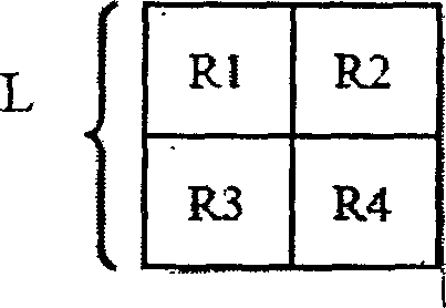
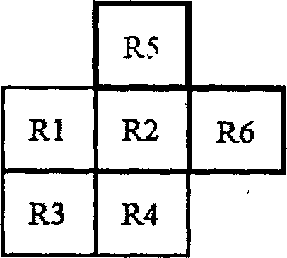
[0049]Step 1: Rasterize the original pattern. The system divides a pattern collaborative design two-dime...


PUM


Abstract

A prediction method of system lock in pattern coordination design includes applying prediction method of expansion, lock and set to help the user of online operation to predict operation region in the future and locking the region in advance; starting up corresponding policy for solving the conflict while conflict is occurred is locking operation.

Description

technical field [0001] The invention relates to the technical field of Internet-based distributed pattern collaborative design, in particular to a method for predicting system locks in pattern collaborative design. Background technique [0002] One of the outstanding achievements of mankind in the 20th century, computer technology has brought human society into the information age. With the continuous deepening of the informationization process, the integration of communication technology, computer and network technology has created a new research field - Computer Supported Cooperative Work CSCW (Computer Supported Cooperative Work). [0003] The diversity of group collaboration methods provides rich content for CSCW research. In the CSCW system, people carry out basic activities such as Communication, Coordination, Collaboration, and Cooperation around the tasks completed together. [0004] CSCW has a wide range of application fields and market prospects. The fields that ...

Claims


Application Information

Patent Timeline
Patent Type & Authority Applications(China)
IPC IPC(8): G06F9/44G06F9/46
Inventor 卜佳俊陈纯杨建旭惠怀海
Owner ZHEJIANG UNIV
Why Eureka
Try Eureka