

Unit for shunting current from bus bars
A busbar and extension technology, applied in the field of busbar electrical conductors, can solve the problems of complex and expensive shunt units
- Summary
- Abstract
- Description
- Claims
- Application Information
AI Technical Summary
Problems solved by technology
Method used
Image

Examples
Embodiment Construction
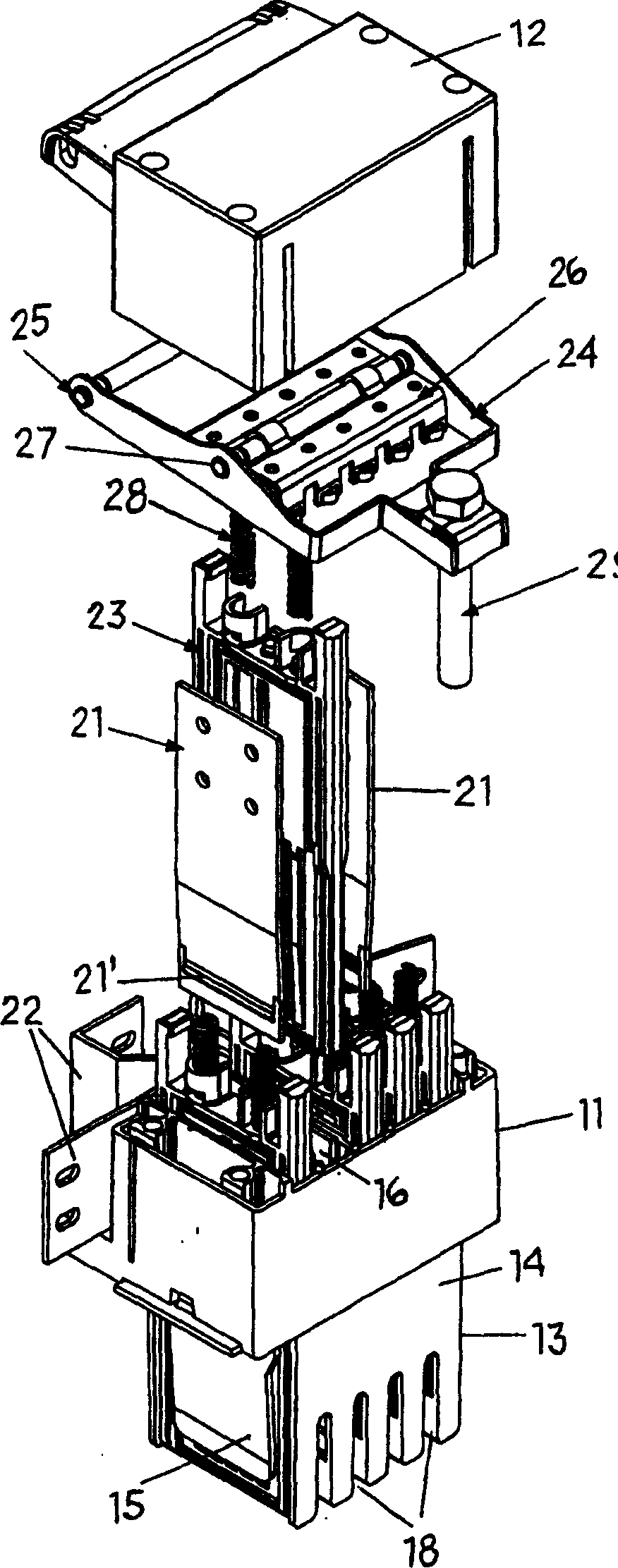
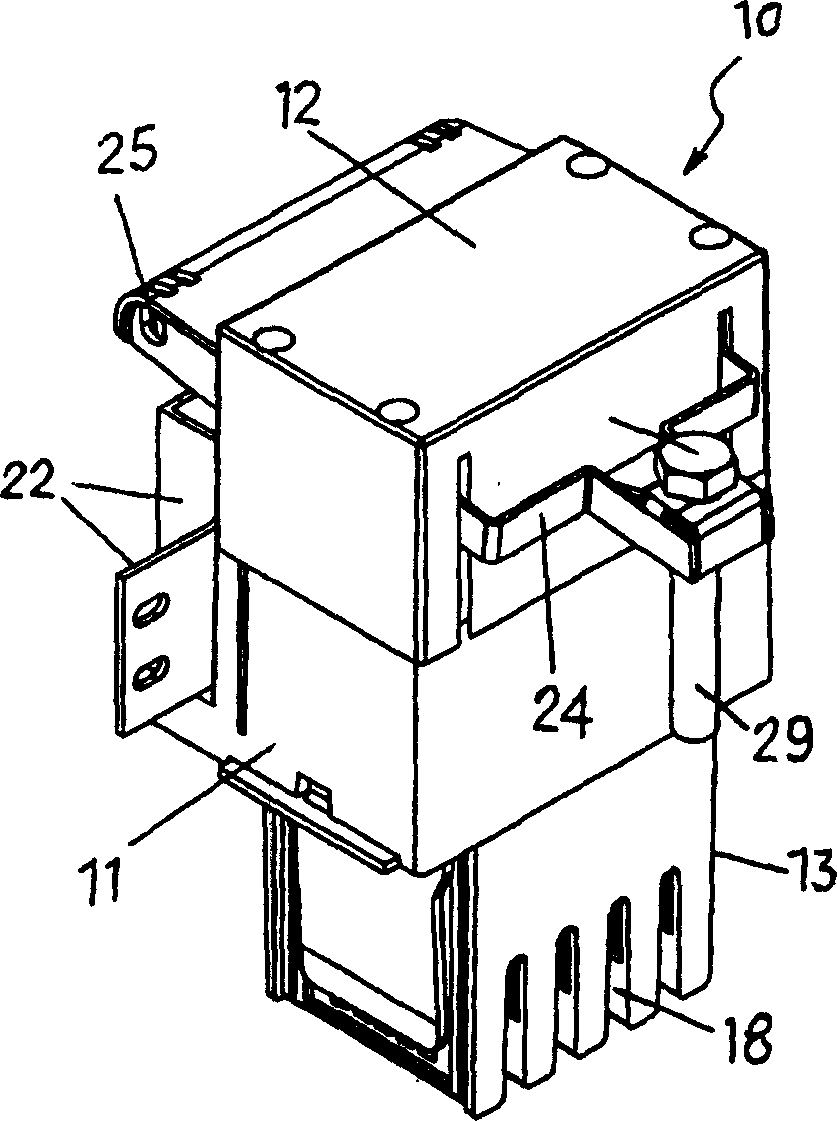
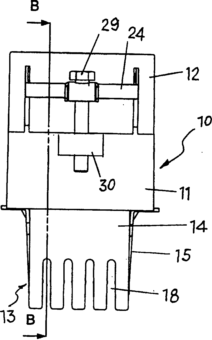
[0021] As shown, the splitter unit or device 10 comprises a substantially square box-shaped housing 11 with a cover 12 at the top and an extension 13 at the bottom which is narrower and Its size depends on the output groove it will be inserted into. This extension 13 is formed by two opposite main rigid walls 14 integral with the housing 11 and two opposite secondary walls 15 interposed and preferably elastic.
[0022] Parallel partitions 16 are conceived in the box-like housing 14 and in the opposite bottom extension 13 which subdivide the interior of the housing and extension into partitions 17 according to the height of the housing 11 and in Extends on a plane parallel to the insertion walls 15 on two opposite sides of the bottom extension 13 . Downwardly open recesses 18 are formed in the two opposing rigid walls 14 of said bottom extension of the housing, these recesses being interposed between the partitions 17, aligned with the partitions, and each Both are dimensione...
PUM
 Abstract
Description
Claims
Application Information