Dual band antenna

A dual-band, antenna technology, used in antennas, resonant antennas, antenna components, etc., can solve problems such as performance differences, insufficient to effectively meet the center frequency, and not suitable for mass production.

Inactive Publication Date: 2005-07-27
E M W ANTENNA CO LTD
View PDF0 Cites 4 Cited by
  • Summary
  • Abstract
  • Description
  • Claims
  • Application Information

AI Technical Summary

Problems solved by technology

In addition, space cannot be secured to meet the needs for different shapes of antennas
In addition, due to the dual-pitch helical structure of the conventional dual-band antenna, dielectric materials of different pitches should be separately connected to the helical portion to be fixedly placed, and the efficiency of the conventional dual-band antenna is deteriorated due to the uneven characteristics of the manufactured antenna, Traditional dual-band antennas are also not suitable for high-volume production due to large performance differences caused by manufacturing variations
In addition, since the bandwidth in conventional dual-band antennas is such as figure 2 As shown, the formation is narrow, so the problem with the traditional dual-band antenna is that it is not effective enough to meet the movement of the center frequency, so that it is not enough to adapt to the environmental changes of the mobile terminal

Method used


Image

  • Dual band antenna
  • Dual band antenna
  • Dual band antenna

Examples


Embodiment Construction

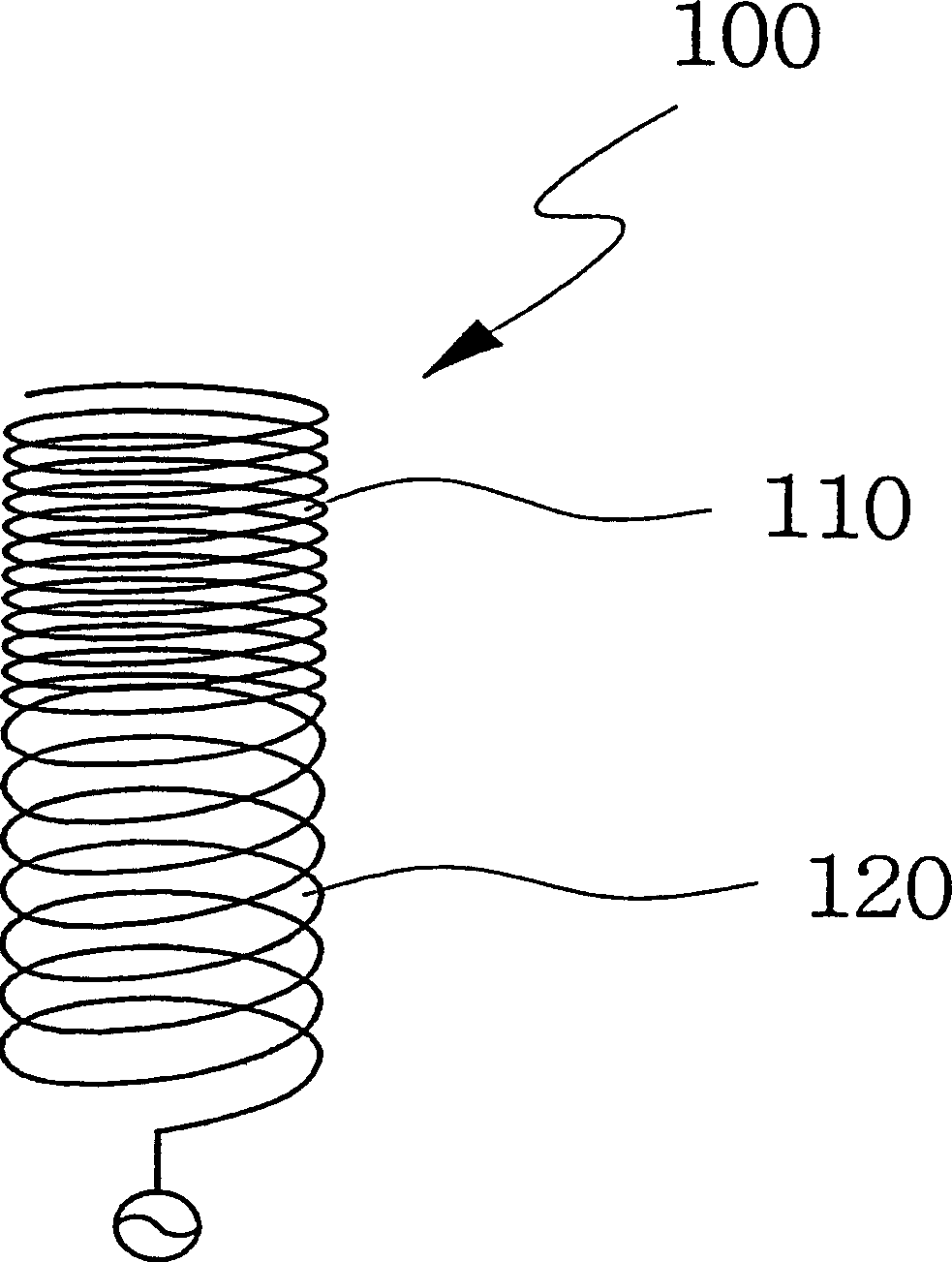
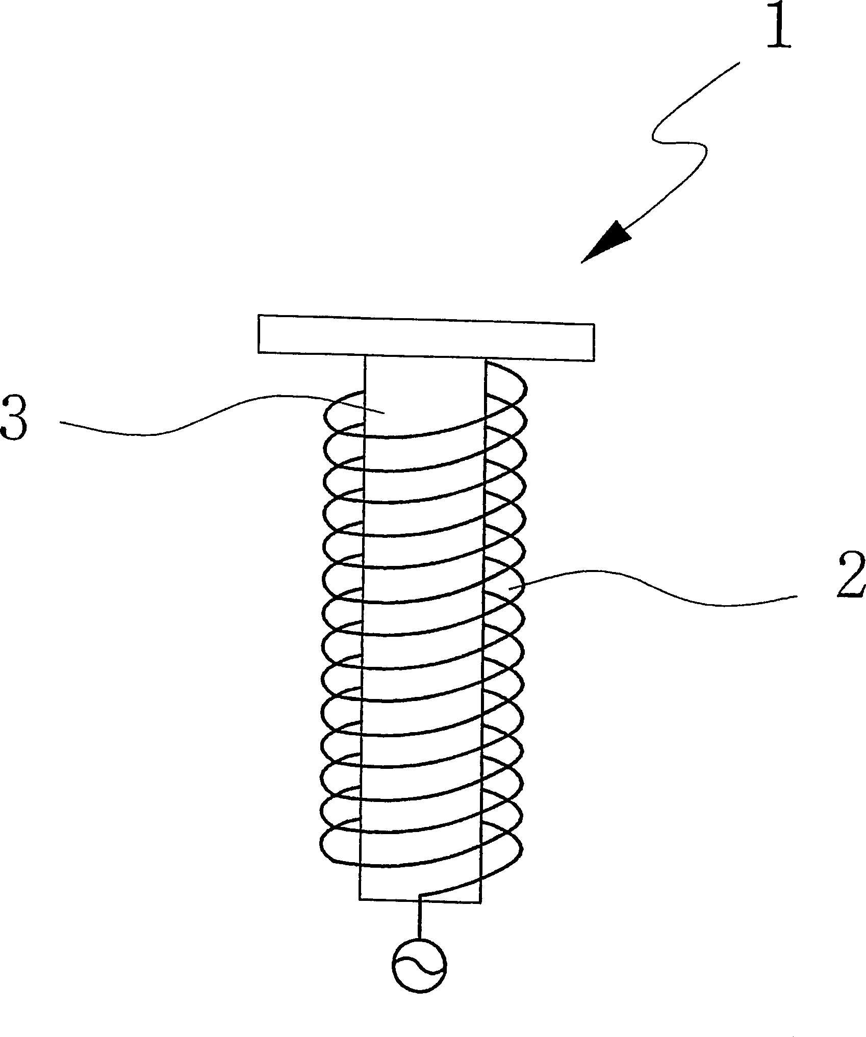
[0016] Preferred embodiments of the present invention will be described in detail below with reference to the accompanying drawings. image 3 is an exemplary view showing the structure of a dual-band antenna to which the technique of the present invention is applied according to a preferred embodiment. Referring to this accompanying drawing, the dual-band antenna 1 to which the technology of the present invention is applied has a mechanically separated and electrically connected structure, wherein a hollow or solid parasitic element is arranged in the internal space of the first member 2, and the first member It is formed by winding a wire, such as a metal wire, several times, and a dielectric material is placed between the parasitic element 3 and the first member 2 .

[0017] at the same time, Image 6 is an exemplary view showing another embodiment of the present invention, wherein the dual-band antenna 1 has a mechanically separated and electrically connected structure, wh...


PUM


Abstract

The present invention relates generally to a dual band antenna, and more particularly to a dual band antenna, in which a hollow or solid parasitic element is disposed inside an antenna formed by winding a wire material several times or bending a strip material several times to have a predetermined shape. The dual band antenna of the present invention can be easily manufactured, and can improve the efficiency thereof and meet a desired bandwidth by overcoming the problem of connecting dielectric materials to helical parts of different pitches to fix the dielectric materials in the prior art, improving the variation of performance resulting from manufacturing variation and designing the dual band antenna to have a maximal size with respect to the shape thereof, thus immediately meeting the movement of a central frequency caused by the various environments of the antenna.

Description

technical field [0001] The present invention relates generally to a dual-band antenna, and more particularly to a dual-band antenna in which a hollow or solid parasitic element is placed inside an antenna which is obtained by winding a wire several times or bending a strip of material Formed several times to have a predetermined shape, allowing the same resonance frequency band to be used without change. Background technique [0002] In a general feeding structure of a conventional small-sized antenna used in wireless communication, antenna feeding is realized by using a contact of a conductive object on a board or a coaxial cable. For monopole antennas, the antenna feed is achieved by contacting the + part with the conductive mechanical part, or simultaneously the antenna feed is through the + and - parts of the coaxial cable. [0003] figure 1 is an exemplary view showing the structure of a conventional dual-band antenna 100 that can be divided into a first helical porti...

Claims


Application Information

Patent Timeline
Patent Type & Authority Applications(China)
IPC IPC(8): H01Q1/36H01Q1/38H01Q1/40H01Q5/00H01Q5/10H01Q9/36H01Q9/40
CPCH01Q9/36H01Q1/362H01Q1/40H01Q5/0062H01Q9/40H01Q5/378
Inventor 柳秉勋成元模梁墓根
Owner E M W ANTENNA CO LTD
Why Eureka
Try Eureka