Method for producing Mn-Zn ferrite

一种制造方法、铁氧体的技术,应用在电感/变压器/磁铁制造、化学仪器和方法、建筑构件在现场的制备等方向,能够解决应用不合适、没有考量饱和磁通密度、不能发挥变压器、电抗器用铁心性能等问题,达到损耗低的效果

Inactive Publication Date: 2005-08-03
TDK CORPARATION
View PDF4 Cites 40 Cited by
  • Summary
  • Abstract
  • Description
  • Claims
  • Application Information

AI Technical Summary

Problems solved by technology

However, although the MnZn-based ferrite disclosed in Japanese Unexamined Patent Application Publication No. 11-3813 has excellent characteristics in the high-frequency band region above about 1 MHz, it is difficult to apply to the frequency band of tens of kHz to hundreds of kHz. not suitable
[0014] In addition, although the saturation magnetic flux density at room temperature is high, if the saturation magnetic flux density decreases in the operating temperature range (80-120°C) of the iron core for general transformers and reactors, the required transformer cannot be exerted. , The performance of the iron core for the reactor
[0015] The MnZn-based ferrite disclosed in Japanese Patent Laid-Open No. 2000-286119 has excellent characteristics of loss in the frequency band of tens of kHz to hundreds of kHz, but does not consider the saturation magnetic flux density at around 100°C

Method used


Image

  • Method for producing Mn-Zn ferrite
  • Method for producing Mn-Zn ferrite
  • Method for producing Mn-Zn ferrite

Examples


Embodiment 1

[0066] Fe will be used as the main component raw material 2 o 3 The powder, MnO powder, ZnO powder, and NiO powder were wet-mixed according to the composition shown in FIG. 1 , and then calcined at the temperature shown in FIG. 1 for 2 hours.

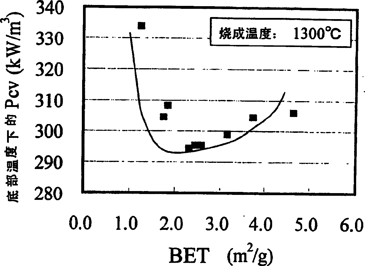
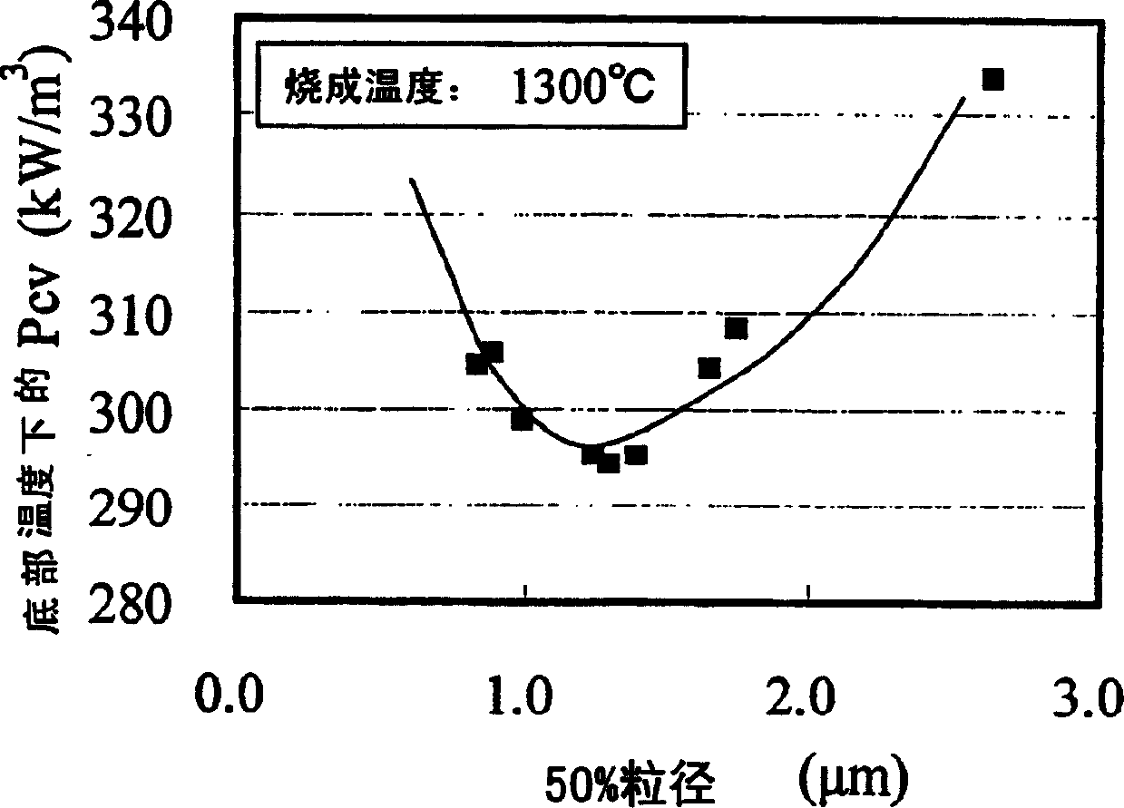
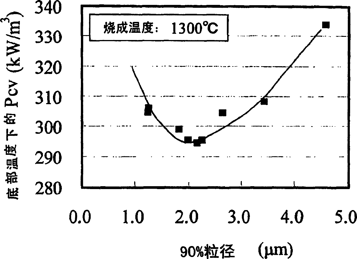
[0067] Next, the calcined product of the main component raw material and the sub component raw material are mixed. As a secondary component raw material, SiO is used 2 Powder, CaCO 3 Powder, Nb 2 o 5 Powder, ZrO 2 Powder and Co 3 o 4 powder. The raw materials of the subcomponents are added to the calcined product of the main component raw materials, and mixed while pulverizing. The specific surface area (BET), 50% particle diameter, and 90% particle diameter of the pulverized mixed powder were measured, and the results are shown in FIG. 1 .

[0068] From Fig. 1, it can be confirmed that the lower the calcining temperature and the longer the pulverization time, the larger the specific surface area of ​​the powder....

Embodiment 2

[0076] The set composition and firing conditions are shown in Fig. 15, and only SiO is added as the first subcomponent 2 and CaCO 3 , In addition, MnZn ferrite was produced in the same manner as in Example 1, and the characteristics were measured in the same manner as in Example 1. The results are shown in FIG. 15 . In addition, the powder properties before firing are as follows:

[0077] BET: 2.5~4.0m 2 / g

[0078] 50% particle size: 0.7~1.5μm

[0079] 90% particle size: 1.0~4.0μm

[0080] Also, Pcv in Fig. 15 represents the loss at the bottom temperature, and B.Temp. represents the bottom temperature.

[0081] As shown in Figure 15, the Fe 2 o 3 When it is as little as 53.5 mol%, the saturation magnetic flux density (Bs) decreases. On the other hand, in Fe 2 o 3 As much as 57.5 mol%, the loss increases.

[0082] Next, when ZnO is as little as 4.5 mol%, the loss increases, while when ZnO is as much as 11 mol%, the saturation magnetic flux densi...

Embodiment 3

[0086] Except for the types and contents of the subcomponents set in FIGS. 16 and 17 , MnZn ferrite was produced in the same manner as in Example 1, and the characteristics were measured in the same manner as in Example 1. The results are shown in FIGS. 16 and 17 . The powder properties before firing are as follows:

[0087] BET: 2.5~4.0m 2 / g

[0088] 50% particle size: 0.7~1.5μm

[0089] 90% particle size: 1.0~4.0μm

[0090] In addition, Pcv at RT in FIG. 17 represents loss at 25°C, Pcv at 100°C represents loss at 100°C, and ΔPcv represents loss at 25°C-loss at 100°C.

[0091] As shown in FIG. 16 , by adding the second subcomponent and the third subcomponent, the saturation magnetic flux density (Bs) can be increased and the loss can be reduced. However, adding too much will decrease the saturation magnetic flux density (Bs) or increase the loss, so it is desirable to add within an appropriate range.

[0092] In addition, as shown in FIG. 17 , by adding a...


PUM

PropertyMeasurementUnit
specific surface areaaaaaaaaaaa
particle diameteraaaaaaaaaa
specific surface areaaaaaaaaaaa

Abstract

The present invention provides a Mn-Zn ferrite which is low in the loss in the frequency range between a few 10 kHz and a few 100 kHz and high in the saturation magnetic flux density in the vicinity of 100°C. The present invention comprises the steps of compacting a powder having a specific surface area (based on the BET method) of 2.0-5.0 m 2 / g and a 50% particle size of 0.7-2.0 µm into a compacted body having a predetermined shape and obtaining a sintered body by sintering the compacted body. Preferably, the Mn-Zn ferrite comprises 54-57 mol-% Fe 2 O 3 , 5-10 mol-% ZnO, more than 0 to 4 mol-% NiO, and the balance substantially being MnO as main constituents.

Description

technical field [0001] The present invention relates to a method for producing MnZn ferrite having high saturation magnetic flux density, high magnetic permeability, and low loss at high temperature (near 100°C). Background technique [0002] In recent years, electronic equipment has been developed toward small size and high output power, and various components have been developed toward high integration and high-speed processing. This requires the power supply line for power supply to be able to carry a large current. [0003] Also, the power cord is required to maintain specified performance even at high temperatures because the power cord is often exposed to heat from components such as a CPU or the like. In addition, the power cord is required to maintain specified performance even under the high ambient temperature conditions of the electronic circuits used in automobiles. [0004] Therefore, transformers and reactors used for power lines are also required to be used a...

Claims


Application Information

Patent Timeline
Patent Type & Authority Applications(China)
IPC IPC(8): C04B35/38C01G49/00C01G53/00C04B35/26H01F1/34H01F41/02
CPCC04B2235/3239C04B2235/5409C04B2235/5445C04B35/6261C04B35/6303C04B35/62675C04B2235/3293C04B2235/3232C01P2004/51C04B2235/77C01G49/0072C04B2235/3279C04B2235/6584C04B2235/3262C01P2002/52C01P2006/42C04B2235/3298C04B2235/3418C04B35/62655C04B2235/5463H01F1/344C04B2235/85C04B2235/3284C04B35/2658C01G53/006C04B2235/3208C01P2004/61C04B2235/3286C01P2006/12C04B35/62645C04B2235/3251C04B2235/3263C04B2235/786C01P2006/10C04B2235/656C04B2235/5436C04B2235/3256C01P2004/62H01F41/0246C04B2235/3244C04B2235/3275E04G17/045
Inventor 福地英一郎柿沼朗高川建弥马场文崇村濑琢
Owner TDK CORPARATION
Why Eureka
Try Eureka