

Deblocking filtering method and apparatus of video frequency or image
A deblocking filter and image technology, applied in the field of electrical digital data processing, can solve the problems of large amount of calculation, high calculation complexity, difficulty in using parallel computing functions, etc., and achieve the effect of reducing storage complexity and calculation complexity
- Summary
- Abstract
- Description
- Claims
- Application Information
AI Technical Summary
Problems solved by technology
Method used
Image

Examples
Embodiment 1
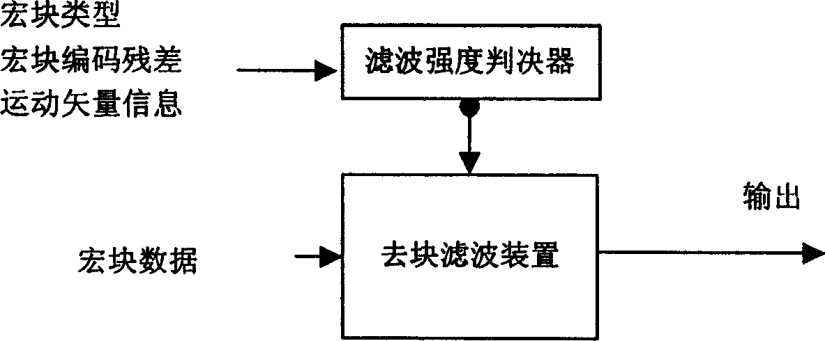
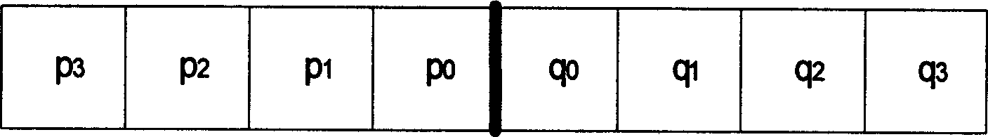
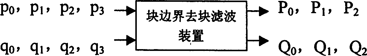
[0019] attached Figure 4 Shows a coding and decoding device for video or image deblocking filtering, including a filtering mode decision device, a deblocking filtering device for performing deblocking filtering on macroblock data, and a time division multiplexing device for time-division output . attached Figure 5 It shows the sample pixels involved in the deblocking filtering performed on the horizontal or vertical boundaries of 4×4 blocks by the deblocking filtering method adopted in the present invention. Among them, the thick line indicates the block boundary that needs to be deblocked and filtered, p 0 ,p 1 ,q 0 ,q 1 Indicates 2 sample pixels on both sides of the block boundary. attached Image 6 Shows a block boundary deblocking filtering device for performing deblocking filtering on a block boundary in an existing deblocking filtering method, p 0 ,p 1 ,q 0 ,q 1 Represents 4 sample pixels input to the block boundary deblocking filter device, P 0 , P 1 , Q ...
Embodiment 2
[0050] attached Figure 4 It shows a coding and decoding device applied to video or image deblocking filtering, including a filtering mode decision device, a deblocking filtering device for performing deblocking filtering on macroblock data, and a time division multiplexing device for time-division output . attached Figure 5 It shows the sample pixels involved in the deblocking filtering performed on the horizontal or vertical boundaries of 4×4 blocks by the deblocking filtering method adopted in the present invention. Among them, the thick line indicates the block boundary that needs to be deblocked and filtered, p 0 ,p 1 ,q 0 ,q 1 Indicates 2 sample pixels on both sides of the block boundary. attached Image 6 Shows a block boundary deblocking filtering device for performing deblocking filtering on a block boundary in an existing deblocking filtering method, p 0 ,p 1 ,q 0 ,q 1 Represents 4 sample pixels input to the block boundary deblocking filter device, P 0 ,...
Embodiment 3
[0080] attached Figure 4 It shows a coding and decoding device applied to video or image deblocking filtering, including a filtering mode decision device, a deblocking filtering device for performing deblocking filtering on macroblock data, and a time division multiplexing device for time-division output . attached Figure 5 It shows the sample pixels involved in the deblocking filtering performed on the horizontal or vertical boundaries of 4×4 blocks by the deblocking filtering method adopted in the present invention. Among them, the thick line indicates the block boundary that needs to be deblocked and filtered, p 0 ,p 1 ,q 0 ,q 1 Indicates 2 sample pixels on both sides of the block boundary. attached Image 6 Shows a block boundary deblocking filtering device for performing deblocking filtering on a block boundary in an existing deblocking filtering method, p 0 ,p 1 ,q 0 ,q 1 Represents 4 sample pixels input to the block boundary deblocking filter device, P 0 ,...
PUM
 Abstract
Description
Claims
Application Information