
Pedal security system

A technology of safety system and pedal, which is applied in the field of pedal safety system of motor vehicles, and can solve problems such as driver injury and passenger injury

Inactive Publication Date: 2005-08-10
FEIKE CABLE CO LTD
View PDF2 Cites 2 Cited by
  • Summary
  • Abstract
  • Description
  • Claims
  • Application Information

AI Technical Summary

Problems solved by technology

As mentioned above in connection with other pedal safety systems, the pedal is now free to move and can also cause injury to the driver
Another disadvantage is that the bearing bushes on which the pedal shafts are mounted are broken into pieces in the event of an accident, which can also lead to injury to passengers

Method used


Image

  • Pedal security system
  • Pedal security system
  • Pedal security system

Examples


Embodiment Construction

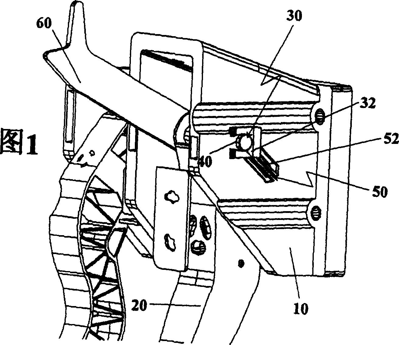
[0021] The present invention relates to a pedal safety system, in particular a pedal safety system for use with a pedal assembly 1 of a motor vehicle.

[0022] It is generally known that motor vehicles are assembled in a unitary structure. Accordingly, the pedal assembly 1 is a component on which three pedals, such as an accelerator pedal, a clutch pedal, and a brake pedal, are mounted.

[0023] An overview of a preferred embodiment of a pedal assembly 1 according to the invention is shown in FIG. 1 . The pedal assembly 1 includes an assembly seat 10 for installing the pedal assembly 1 on a motor vehicle. Moreover, the component seat 10 is used to receive and install the pedal 20 . Depending on the type of motor vehicle, the pedal assembly 1 may comprise a different number of pedals 20 . According to FIG. 1 , the preferred embodiment of the pedal assembly 1 includes two different pedals 20 mounted on the assembly seat 10 .

[0024] The pedal 20 mounted on the pedal assembl...


PUM


Abstract

The present invention relates to a pedal security system for pedal mounting, particularly for motor vehicles, comprising a pedal rotatably mounted by means of a pedal axis, an opening for receiving and retaining said pedal axis which is connected with an expandable slot wherein said expandable slot receives said pedal axis by exceeding a mechanical limit load of the pedal axis.

Description

technical field [0001] The present invention relates to pedal safety systems, and more particularly to pedal safety systems for motor vehicles, which minimize the risk of injury to the driver in the event of an accident. Background technique [0002] In the event of a frontal collision of the motor vehicle, existing pedals are pushed, for example, in the direction of the driver. This is mainly due to the connection of the pedal to, for example, the clutch or brake system of the motor vehicle via a connecting rod. In the event of an accident, where the motor vehicle or parts of the vehicle structure are pushed towards the driver, the pedals may also move towards the driver through the movement of the connecting rod. This can result in serious injury to the driver, which can be prevented with the pedal safety system. Therefore, improving the safety of motor vehicle passengers, especially the safety of drivers is always a concern of the automobile industry. [0003] The prio...

Claims


Application Information

Patent Timeline
Patent Type & Authority Applications(China)
IPC IPC(8): B60R21/02B60R21/09B60T7/06G05G1/327
CPCY10T74/20528Y10T74/20534B60T7/065G05G1/327B60R21/09Y10T74/20888Y10T70/5889
Inventor 若姆·普拉特特拉达斯戴维·阿隆索·格拉斯
Owner FEIKE CABLE CO LTD
Learn More