Cutting equipment

A technology of outer cover and rotating brush, which is applied in the cutting of textile materials, cleaning methods using tools, textiles and papermaking, etc., and can solve problems such as inability to obtain cleaning effects

Inactive Publication Date: 2005-08-10
SHIMA SEIKI MFG LTD
View PDF1 Cites 34 Cited by
  • Summary
  • Abstract
  • Description
  • Claims
  • Application Information

AI Technical Summary

Problems solved by technology

Therefore, cleaning by vacuum suction disclosed in JP-A-5-77198, or cleaning by ro

Method used


Image

  • Cutting equipment
  • Cutting equipment
  • Cutting equipment

Examples


Embodiment Construction

[0038] Hereinafter, preferred embodiments of the present invention will be described in detail with reference to the accompanying drawings.

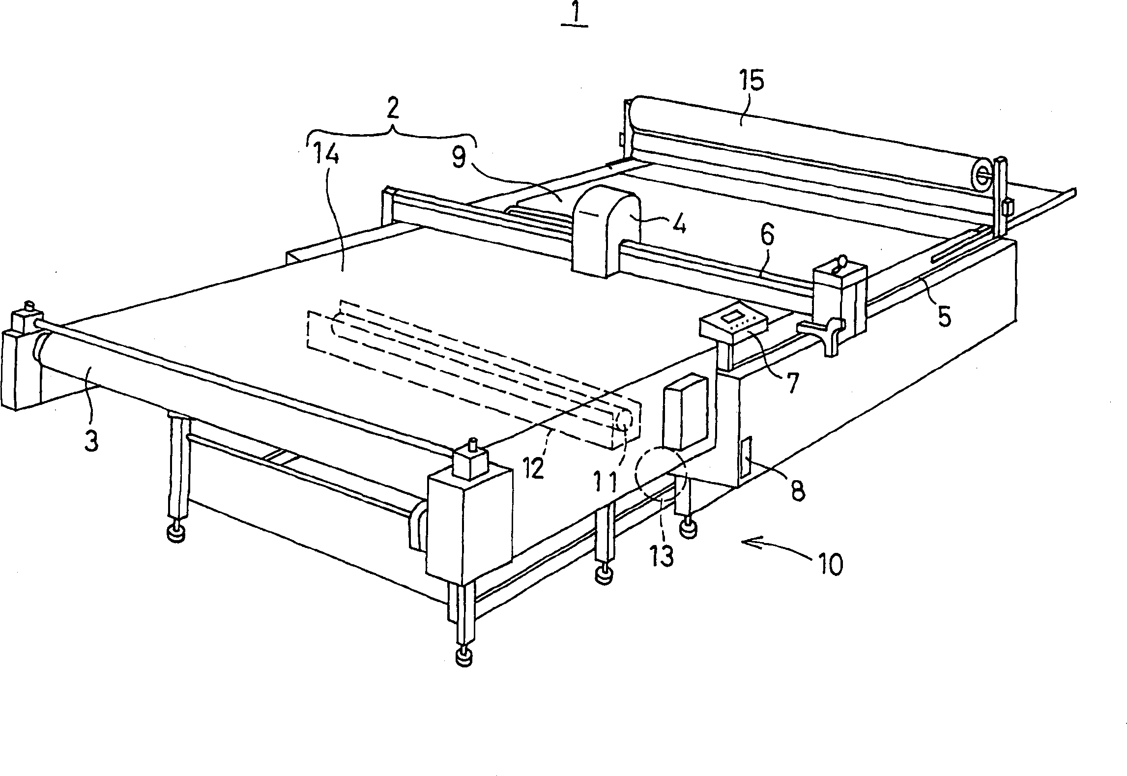
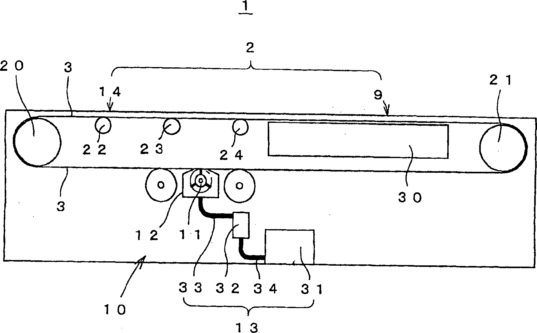
[0039] figure 1 It is a perspective view showing a simplified appearance structure of a cutting device 1 which is an embodiment of the present invention. The cutting device 1 forms a cutting workbench 2 by a grid-shaped recirculating belt 3 . In the cutting device 1 , a sheet such as a cloth to be cut is sucked and held on a conveyor-type cutting table 2 , and is cut by a cutting head 4 . In addition, sheets are omitted in the drawings. The cutting head 4 is supported by a movable rail 6 capable of reciprocating along the fixed rail 5 in the conveying direction of the belt 3 , and is capable of reciprocating along the movable rail 6 in a direction perpendicular to the conveying direction. The controller 7, according to the cutting data recorded on the recording medium such as the floppy disk inserted in the data slot 8, will combine t...


PUM


Abstract

The invention relates to a method aiming at cleaning the clipping chip in high efficiency even in a clipping device with a conveyor belt type clipping workable formed with grip-shaped belt. A cleaning device (10) is arranged on the lower part of the circulation route of the grip-shaped belt (3) and is used for cleaning under the circulatory movement of the belt (3) to remove the adhered clipping chip. The cleaning device (10) comprises a mechanism (11) which enables surface contact between the brushes and the belt (3) which can move relatively, an external housing (12) which covers the surface part connecting with the brush mechanism (11) from the outside and an air intake mechanism (13). The air intake mechanism (13) is used for inhaling the air in the external housing (12), so the clipping chip separated from the belt (3) surface by the brush mechanism (11) can be suck in together with the air and then discharged out of the external housing (12), and then the belt (3) surface can be cleaned reliably.

Description

technical field [0001] The present invention relates to a cutting device which forms a conveyor-type cutting table using an air-permeable grid-like belt to cut sheets such as cloth, and particularly relates to a structure for cleaning to prevent mesh clogging. Background technique [0002] Conventionally, a cutting device is used to cut out parts used for sewing clothes or the like from a soft sheet such as cloth. As a cutting device that improves cutting productivity, an automatic cutting device that holds a sheet on a cutting table by vacuum suction and can automatically cut according to preset cutting data is used. When the sheet is cut with a cutter, cutting waste such as cotton yarn is generated. When the generated cutting scraps adhere to the cutting table, there is a possibility that they may adhere to the sheet to be trimmed later. For example, when cuttings from a bright-colored sheet such as white adhere to a dark-colored sheet such as black, or when the light-da...

Claims


Application Information

Patent Timeline
IPC IPC(8): B08B1/02B08B1/04B08B5/04B26D7/18D06G1/00D06H7/02
CPCD06G1/00B08B1/04B08B5/046B26D7/1863B26D2007/208
Inventor 森田敏明
Owner SHIMA SEIKI MFG LTD
Why Eureka
Try Eureka