Swirl spouting device for drying sludge

A sludge drying and drying technology, applied in the direction of dewatering/drying/concentrating sludge treatment, etc., can solve the problems of low drying rate, increased deflagration, easy air leakage, etc., to reduce the possibility of sticking to the wall and reduce airflow Good resistance and device airtightness

Inactive Publication Date: 2005-08-17
JIANGSU TIANYING ENVIRONMENTAL PROTECTION ENERGY COMPLETE EQUIP CO LTD +1
View PDF0 Cites 6 Cited by
  • Summary
  • Abstract
  • Description
  • Claims
  • Application Information

AI Technical Summary

Problems solved by technology

The rotary drum dryer mainly has the following technical problems: 1. It is easy to leak air, which increases the oxygen content of the drying medium. For the drying of sludge whose combustion performance is similar to that of lignite and its volatility is higher than that of lignite, it increases the possibility of deflagration. sex
2. It is easy to stick to the wall. The sludge has strong viscosity and is easy to adhere to the wall of the drum, which will affect the drying efficiency and even cause the equipment to fail to operate normally.
3. The device is huge, the heat dissipation loss is large, and the drying heat efficiency is low
The airtightness of the fluidized bed dryer is better than that of the rotary drum dryer, but it is generally used for the drying of less viscous sludge (such as general municipal sewage sludge), and for the drying of more viscous sludge (such as Biochemical sludge) often adopts the technology of first granulation and then drying, the equipment cost is high and the system is complicated
And its drying rate is not large, the intake temperature cannot be too high, and the drying heat efficiency is also low

Method used


Image

  • Swirl spouting device for drying sludge
  • Swirl spouting device for drying sludge
  • Swirl spouting device for drying sludge

Examples


Embodiment Construction

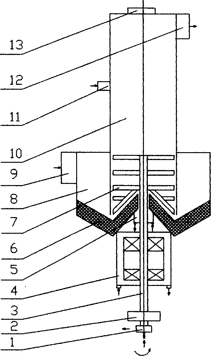
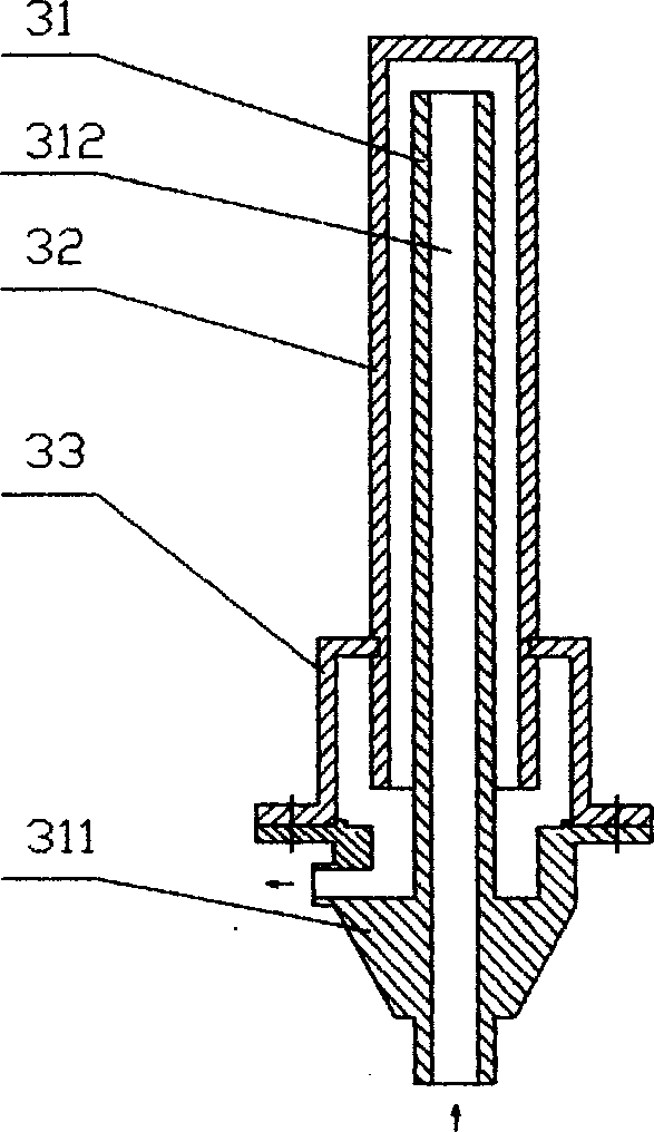
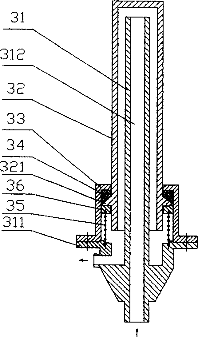
[0018] A swirling jetting device for sludge drying, which is composed of a main tower body 10, an air chamber 8, a transmission shaft 3 and a drying and stirring blade 7. The air chamber 8 is arranged at the lower part of the main tower body 10, and the drying and stirring blade 7 It is arranged on the transmission shaft 3, the main tower body 10 is provided with a feeding port 11 and an air outlet 12, and an air inlet 9 is arranged on the air chamber 8. The axial section of the bottom surface of the air chamber 8 is "W" The air port 9 is a tangential air inlet, the main tower body 10 is located above the "W"-shaped bottom of the air chamber 8 and the lower part of the main tower body 10 extends into the air chamber 8, and the exhaust port 12 is in the same direction as the air inlet 9 The rotating tangential exhaust port, the above-mentioned transmission shaft 3 is composed of a central inner shaft 31, a central outer shaft 32 and a connecting sleeve 33, the central outer shaf...


PUM


Abstract

The sludge drying cyclonic spouting apparatus includes main tower body, air chamber, driving shaft and drying and stirring paddle. The air chamber is set in the lower part of the main tower body, drying and stirring paddle is set onto the driving shaft, the air chamber has tangent air inlet port and bottom with W-shaped axial section, and the main tower body over the W-shaped bottom of the air chamber with its lower part extending into the air chamber, and has material feeding port and air outlet port in the upper part as well as tangent air exhaust port and air inlet port rotating in the same direction. The present invention has the high tightness, high drying efficiency, low power consumption, sterilization effect, no jamming and simple apparatus.

Description

technical field [0001] The present invention relates to a drying device, in particular to a swirling jet device for sludge drying for treating sludge. Background technique [0002] At present, most of the sludge drying adopts rotary drum dryer or fluidized bed dryer. The rotary drum dryer mainly has the following technical problems: 1. It is easy to leak into the air, which increases the oxygen content of the drying medium. For the drying of sludge whose combustion performance is similar to that of lignite, its volatility is higher than that of lignite, which increases the possibility of deflagration. sex. 2. It is easy to stick to the wall, the viscosity of the sludge is strong, and it is easy to adhere to the wall of the drum, thereby affecting the drying efficiency and even making the equipment unable to operate normally. 3. The device is huge, the heat dissipation loss is large, and the drying thermal efficiency is low. The airtightness of th...

Claims


Application Information

Patent Timeline
Patent Type & Authority Applications(China)
IPC IPC(8): C02F11/12
Inventor 葛仕福郭宏伟鲁维加
Owner JIANGSU TIANYING ENVIRONMENTAL PROTECTION ENERGY COMPLETE EQUIP CO LTD
Why Eureka
Try Eureka