Device for detecting tightening of band of paper money binding machine

A detection device and banknote binding machine technology, applied in packaging, packaging protection, paper product packaging, etc., can solve the problems of loud noise and high manufacturing cost, and achieve the effect of reducing production cost and simple detection structure

Inactive Publication Date: 2005-08-24
沈新
View PDF0 Cites 3 Cited by
  • Summary
  • Abstract
  • Description
  • Claims
  • Application Information

AI Technical Summary

Problems solved by technology

[0002] The banknote binding belt of the existing banknote binding machine moves under the drive of the driving wheel and the driven wheel to tighten the binding belt, so that the ironing head part performs high-temperature ironing on the tightened banknote belt to bind the banknotes. A complex mechanical structure is adopted. Under the action of tension at the moment when the banknote binding belt is tightened, the mechanical structure moves in the opposite direction to generate a tension signal depending on the gap left. When the mechanical structure is reset, the sound is louder and the production The cost is also higher

Method used


Image

  • Device for detecting tightening of band of paper money binding machine
  • Device for detecting tightening of band of paper money binding machine
  • Device for detecting tightening of band of paper money binding machine

Examples


Embodiment Construction

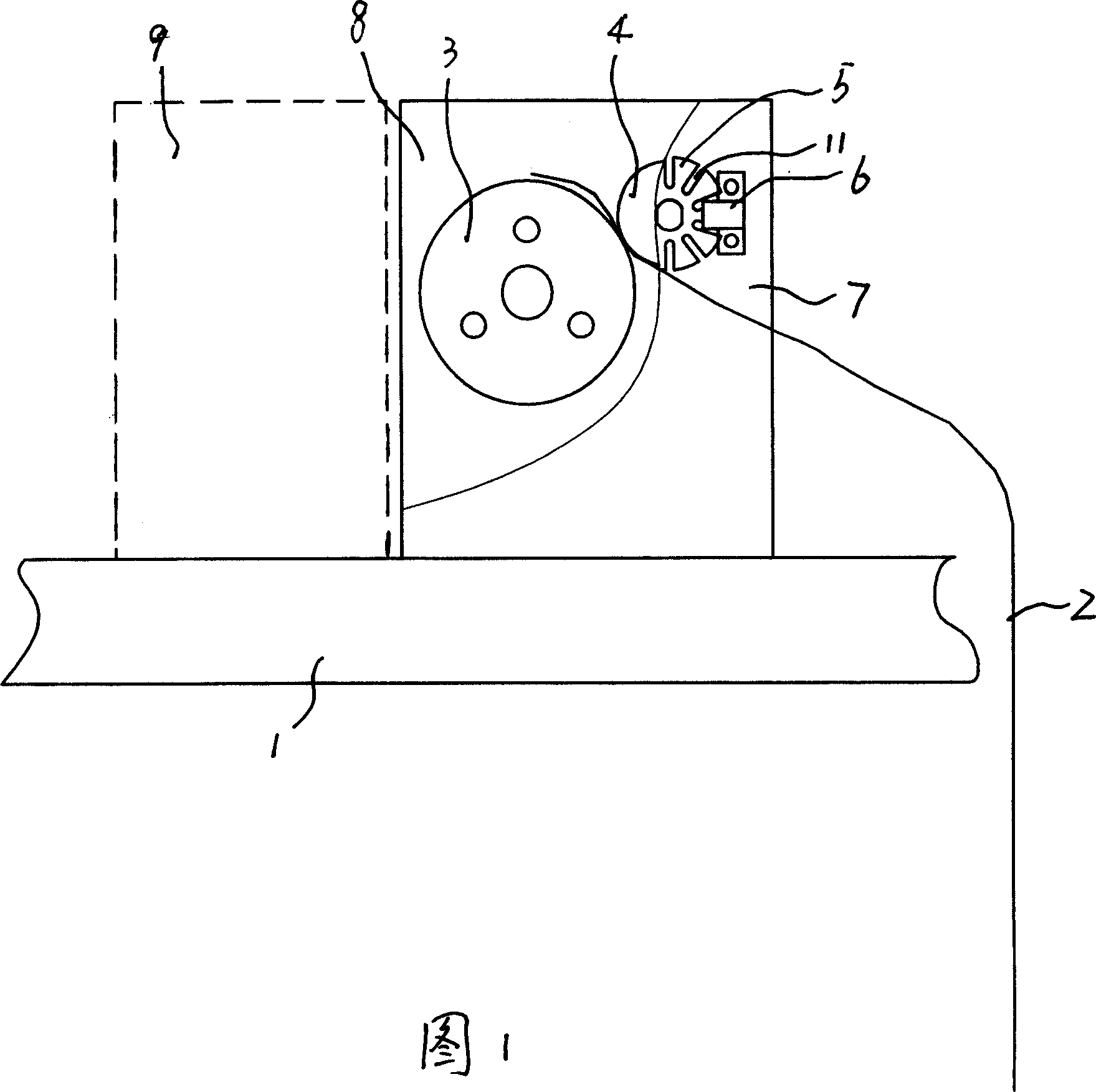
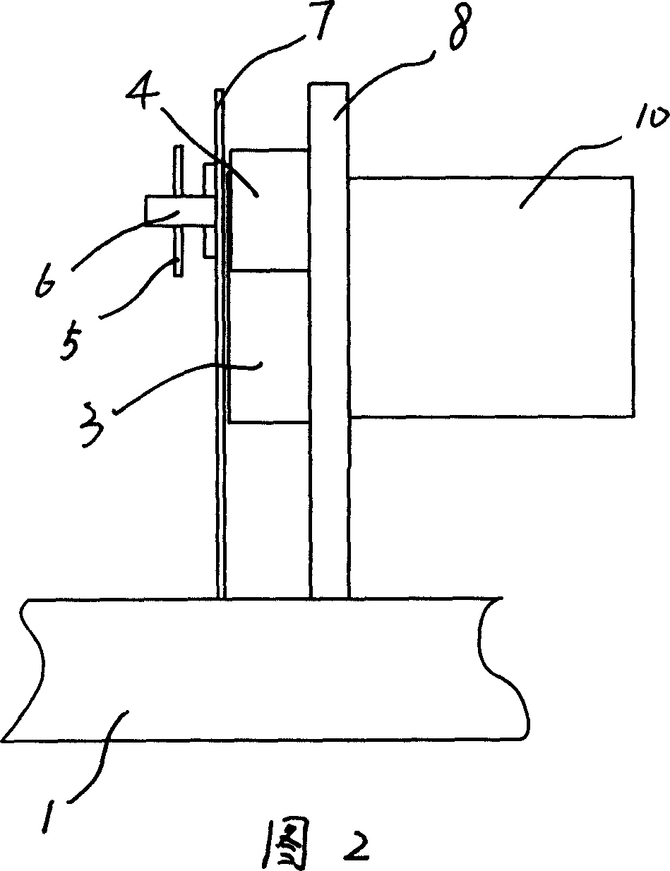
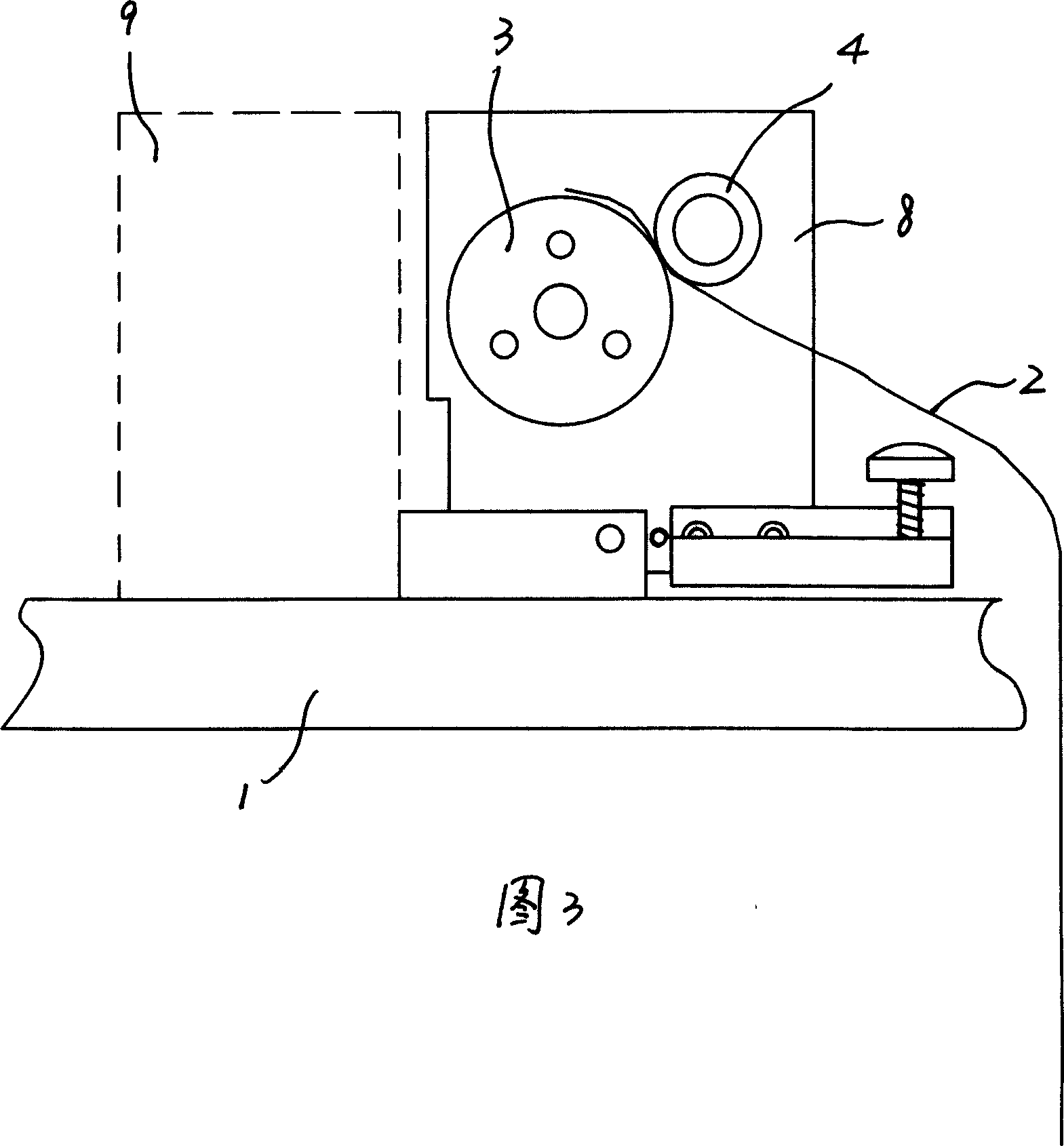
[0011] Referring to accompanying drawing 1-accompanying drawing 3, a kind of take-up detection device of banknote binding machine, comprises the driving pinch wheel 3 and the driven wheel that are arranged on the frame 1, the axis line of described driving pinch wheel 3 and The axis lines of the driven wheels are parallel. The driven wheel has a plurality of grating holes 11 distributed along the circumferential direction, and the outer circumferential surface of the driving pinch wheel 3 is in relative rolling contact with the outer circumferential surface of the wheel body of the driven wheel, and the two The outer peripheral surface is used for clamping and driving the banknote binding belt 2 to move, and the driving pressure belt wheel 3 is connected with the power output mechanism.

[0012] In the embodiment shown in accompanying drawing 1-accompanying drawing 2, described driven pulley comprises driven pinch pulley 4 and take-up grating sheet 5 that is fixedly connected ...


PUM


Abstract

A tightening-up detecting unit for the paper money tying belt is composed of a machine frame, a belt pressing drive wheel, a driven wheel with multiple raster hole, and an optical coupling consisting of an emitting head and a receiving head, which are arranged at both sides of said raster hole. After said belt is tightened up, the driven wheel is stopped and the motor is turned off.

Description

technical field [0001] The invention relates to a banknote binding machine for binding banknotes. Background technique [0002] The banknote binding belt of the existing banknote binding machine moves under the drive of the driving wheel and the driven wheel to tighten the binding belt, so that the ironing head part performs high-temperature ironing on the tightened banknote belt to bind banknotes. A complex mechanical structure is adopted. Under the action of tension at the moment when the banknote binding belt is tightened, the mechanical structure moves in the opposite direction to generate a tightening signal relying on the gap left. When the mechanical structure is reset, the sound is louder and the production The cost is also higher. Contents of the invention [0003] The object of the present invention is to provide a tape-in ​​detection device of a banknote binding machine, which has a simple structure. [0004]...

Claims


Application Information

Patent Timeline
Patent Type & Authority Applications(China)
IPC IPC(8): B65B27/08B65B57/02
Inventor 沈新樊逸清
Owner 沈新
Why Eureka
Try Eureka