Tape cartridge of compatible type

a technology of compatible type and tape cartridge, which is applied in the field of compatible type tape cartridge, can solve the problems of complicated inner structure of tape drive, higher cost, and complex structure, and achieve the effect of simplifying the structure of tape end detection and reducing the number of sensor elements

Inactive Publication Date: 2008-05-27
HITACHT MAXELL LTD
View PDF21 Cites 2 Cited by
  • Summary
  • Abstract
  • Description
  • Claims
  • Application Information

AI Technical Summary

Benefits of technology

[0009]An object of the present invention is to enable to perform light detection of tape ends of compatible type tape cartridges with different widths thereof in common by minimum necessary light emitting element and light receiving element that are disposed in a tape drive, so as to simplify a detection structure of the end of the tape to be provided in the tape drive, and to decrease the manufacturing cost.
[0023]According to the first aspect of the present invention, with the small tape cartridge C1 or the large tape cartridge C2 mounted in the tape drive, with respect to the tape drive, the passages for light injection 15 and the passages for light ejecting 16 in the large and small tape cartridges C1 and C2 have a prescribed position relation. Accordingly, as show in FIG. 3 and FIG. 5, it is sufficient that a set of a light emitting element 22 and a light receiving element 23 is positioned on the right and left side of the tape drive respectively in response to the passage for light injection 15 and the passage for light ejecting 16, so that it is possible to simplify a tape end detection structure to be disposed on the side of the tape drive.
[0024]According to the second aspect of the present invention, for example, when the passages for light ejecting 16 in the large and small tape cartridges C1 and C2 are located at the level of the prescribed distance F with the lower surface of the case of the main body 1 as the reference surface S, if the light receiving elements 23 on the side of the tape drive to face the passages for light ejecting 16 are positioned for each one on the right and left sides as shown in FIG. 8 and FIG. 9, the light receiving element 23 can correspond to the large and small tape cartridges C1 and C2. In this case, the height of the passage for light injection 15 viewed from the lower surface of the case of the main body 1 is different between the large and small tape cartridges C1 and C2, the light emitting elements 22 on the side of the tape drive may be positioned for two right and left or only one light emitting element 22 on right and left may be moved respectively. On the contrary, for example, when the passages for light injection 15 in the large and small tape cartridges C1 and C2 are located at the level of the prescribed distance F from the reference surface S with the upper surface of the case of the main body 1 as the reference surface S, the light emitting elements 22 on the side of the tape drive to face the passages for light injection 15 may be positioned for each one on the right and left sides. In this case, the light receiving elements 23 may be disposed right and left for each two. In any case, as compared to a conventional case such that two light emitting elements 22 and two light receiving elements 23 are disposed, it is possible to decrease the number of the sensor elements, and a complicated structure to move the light emitting element 22 and the light receiving element 23 individually is not needed.

Problems solved by technology

Therefore, when making the large and small tape cartridges with different widths of the cases compatible, in response to the passage for light injection and the passage for light ejecting of the large and small tape cartridges, two dedicated light emitting elements and two dedicated light receiving elements are disposed on the right and left sides of the tape drive respectively, namely, four elements are disposed in total, resulting in making the inner structure of the tape drive complicated and higher cost.
In this case, however, a driving mechanism is needed and this makes the structure more complicated.

Method used


Image

  • Tape cartridge of compatible type
  • Tape cartridge of compatible type
  • Tape cartridge of compatible type

Examples


embodiment 1

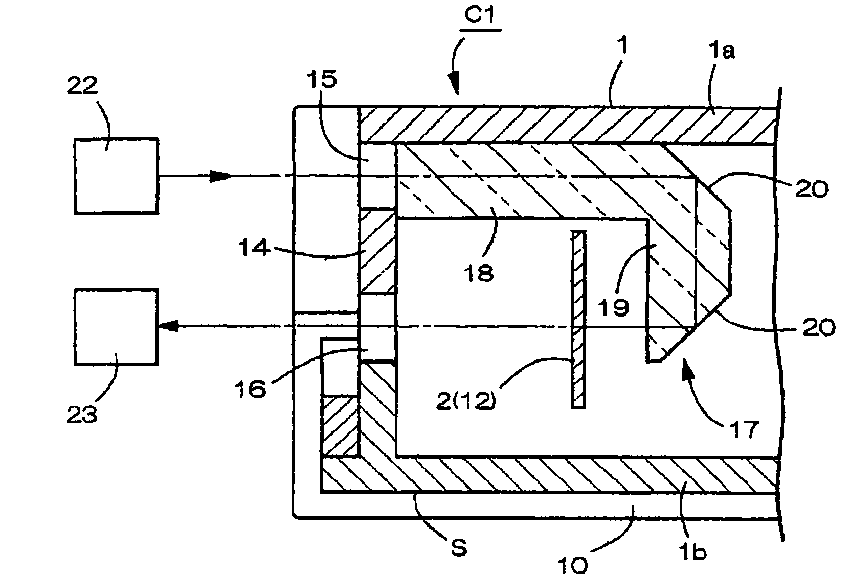
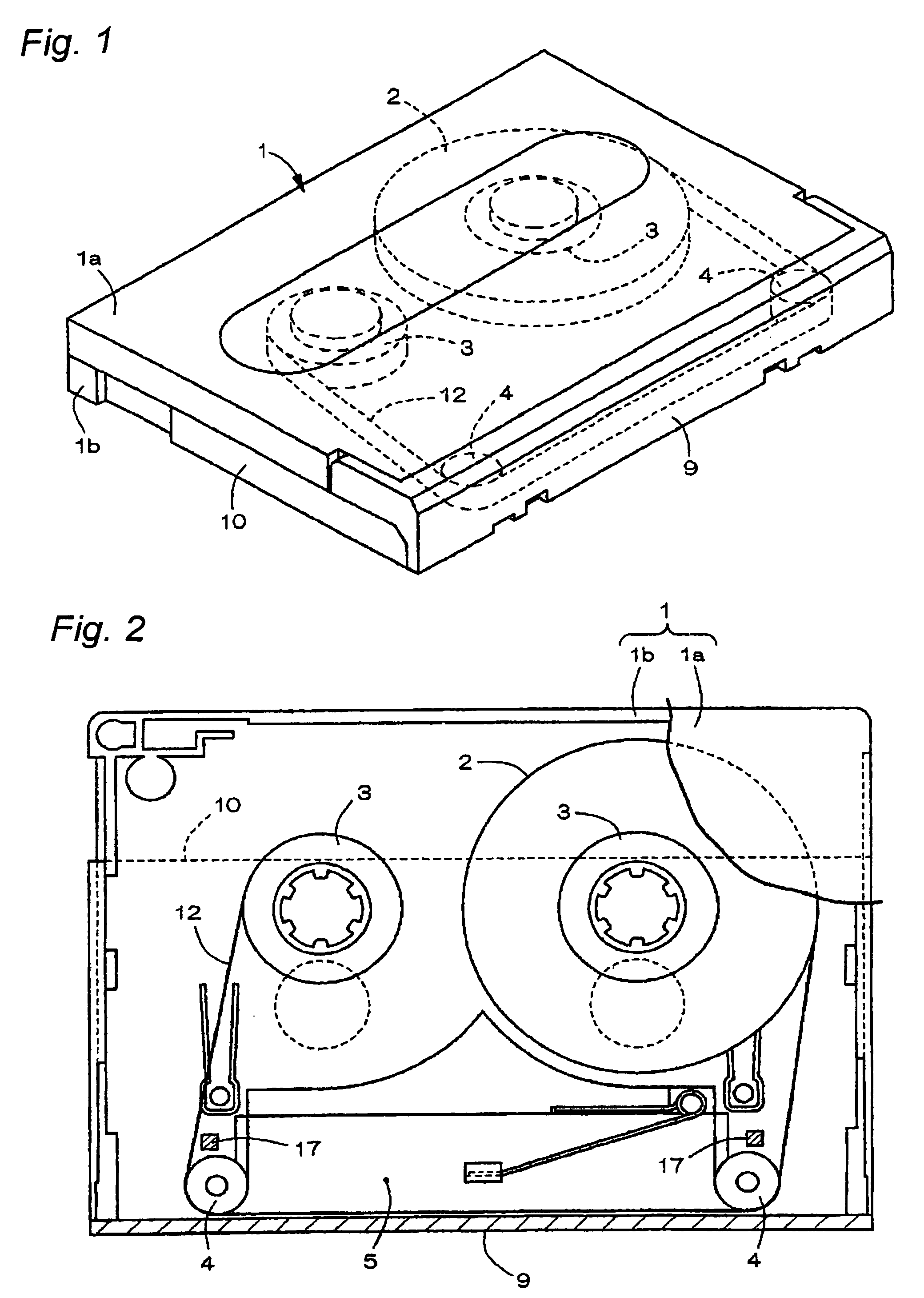
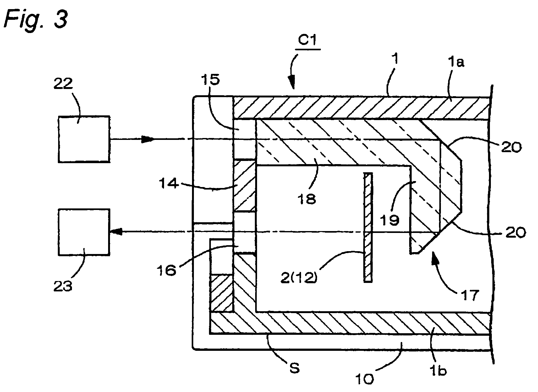
[0040]FIGS. 1 to 5 show a first embodiment of a tape cartridge according to the present invention. FIGS. 1 to 3 show a tape cartridge C1 of a small size among tape cartridges of a compatible type. In this tape cartridge C1, a pair of right and left hubs 3 for winding a tape 2 is arranged in a case of a main body 1. A tape 2 winded off from one hub 3 is winded around the other hub 3 via tape guides 4 that are arranged on the front, right, and left of the case of the main body 1.

[0041]The case of the main body 1 is formed as a hollow box by connecting an upper case 1a and a lower case 1b that are divided into two upward and downward face-to-face. On a bottom wall of the lower case 1b, driving shaft insertion holes are opened corresponding to the right and left hubs 3 and 3.

[0042]Between right and left tape pullout ports, a pocket 5 for loading a tape of which lower surface and front surface are released, is provided. In front of the case of the main body 1, a front cover 9 to cover th...

embodiment 2

[0058]According to the above-described first embodiment, the levels of the passage for light injection 15 and the passage for light ejecting 16 are decided with the lower surface of the case of the main body 1 of the large and small tape cartridges C1 and C2 as the reference surface S, however, the upper surface of the case of the main body 1 of the large and small tape cartridges C1 and C2 may be defined as the reference surface S. FIGS. 6A and 6B show the second embodiment in this case, and the passage for light injection 15 is formed at the prescribed distance F lower from the reference surface 5, namely, the upper surface of the case. Additionally, in the large and small tape cartridges C1 and C2, the adjacent spaces E1 in the upper and lower directions between the passage for light injection 15 and the passage for light ejecting 16 are set to be equal. Since other structures are the same as the first embodiment, the same reference numerals are given to the same members and thei...

embodiment 3

[0059]FIGS. 7 to 9 show a third embodiment of a tape cartridge according to the present invention. According to this third embodiment, in the above-described tape cartridge of the compatible type, as show in FIGS. 7A and 7B, the passages for light ejecting 16 of the large and small tape cartridges C1 and C2 are formed at the same levels at the prescribed distance F from the reference surface S with the lower surface of the case of the main body 1 as the reference surface S. Additionally, in the large and small tape cartridges C1 and C2, the adjacent spaces E1 and E2 in the upper and lower directions between the passage for light injection 15 and the passage for light ejecting 16 are set to be different in response to a difference of the upper and lower widths measurements of the cases of the main body 1 of the large and small tape cartridges C1 and C2.

[0060]In other words, in the small tape cartridge C1, the opening positions (namely, the adjacent space E2) of the passage for light ...


PUM

PropertyMeasurementUnit
depthaaaaaaaaaa
depthaaaaaaaaaa
depthaaaaaaaaaa

Abstract

A tape cartridge capable of recording and reading out large and small tape cartridges with different widths is provided. The tape cartridge comprises a pair of right and left hubs for winding a tape which is winded off from one hub and is wound around the other hub via tape guides. A passage for light injection and a passage for light ejecting of the tape end detection light are opened respectively on a side wall of a case of a main body facing a tape traveling path between the tape guide and the hub, and an optical path inverted body facing a pair of passages across the tape traveling path is arranged in the case of the main body. One of the passages for light injection and the passages for light ejecting in the large and small tape cartridges is formed at a prescribed distance from the reference surface.

Description

[0001]This Nonprovisional application claims priority under 35 U.S.C. § 119(a) on patent application No(s). P 2003-356217 & P 2003-381009 filed in Japan on Oct. 16, 2003 & Nov. 11, 2003; respectively, the entire contents of which are hereby incorporated by reference.BACKGROUND OF THE INVENTION[0002]1. Field of the Invention[0003]The present invention relates to a tape cartridge of a compatible type capable of recording and reading out large and small tape cartridges with different widths (thickness measurements from upper face and lower face of the tape cartridges) in common with the same tape driver.[0004]2. Description of the Related Art[0005]It is known to public that large and small tape cartridges with different widths of their body cases can be recorded and read out in common with the same tape drive in this kind of tape cartridge (refer to: JP-A-5-250841 (paragraph 0022, FIG. 1) and JP-A-7-6558 (paragraph 0020, FIG. 1)). According to the tape cartridge disclosed in JP-A-5-250...

Claims


Application Information

Patent Timeline
Patent Type & Authority Patents(United States)
IPC IPC(8): G11B23/087G11B15/08G11B25/06
CPCG11B15/08G11B23/08714G11B25/066
Inventor AMANO, KOSUKENISHIWAKI, TOSHIROOTA, KENJIYASUI, AKIHIRO
Owner HITACHT MAXELL LTD
Why Eureka
Try Eureka