
Wireless relay system, wireless relay apparatus, and wireless relay method

一种无线中继、无线局的技术,应用在无线中继系统,无线中继装置领域,能够解决接收机噪声变大、副载波噪声功率大、接收装置误码率变高等问题,达到高数据中继、防止中继遗漏、高品质的效果

Inactive Publication Date: 2005-08-24
NTT DOCOMO INC
View PDF5 Cites 22 Cited by
  • Summary
  • Abstract
  • Description
  • Claims
  • Application Information

AI Technical Summary

Problems solved by technology

[0016] However, in the coupling loop interference wave cancellation method disclosed in the above-mentioned Japanese Patent Laid-Open No. 2003-174392, there is a problem that the noise of the receiver becomes larger.
[0017] In addition, in the coupling ring interference wave cancellation method disclosed in Japanese Patent Laid-Open No. 2003-298548, since the signal received by the wireless relay device is weaker, it needs to be amplified by a large factor before sending, so the noise power of some subcarriers It is more likely to be over-amplified and sent
Therefore, it is difficult to suppress the oscillation due to parasitic to a small level
[0018] In addition, in the coupling loop interference wave canceling method disclosed in JP-A-2001-186073, since interference is added to a signal that should be transmitted, there is a problem that the bit error rate of the receiving device is likely to increase.
[0019] In addition, in the coupling loop interference wave cancellation method disclosed in Japanese Patent Laid-Open No. 8-331016, since the channel estimation value depends on the frequency used, in addition to the problem of deterioration of the channel estimation accuracy of the coupling loop interference wave, it is also necessary to provide coupling Frequency band for ring interference wave estimation
[0020] In addition, in the coupling loop interference wave cancellation method disclosed in JP-A-2000-244382, there is a problem that the communication between the transmitting device and the receiving device is temporarily interrupted at an unpredictable timing of the transmitting device.

Method used


Image

  • Wireless relay system, wireless relay apparatus, and wireless relay method
  • Wireless relay system, wireless relay apparatus, and wireless relay method
  • Wireless relay system, wireless relay apparatus, and wireless relay method

Examples


no. 1 Embodiment approach

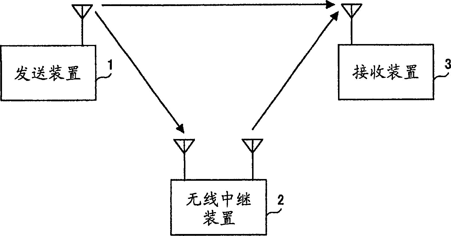
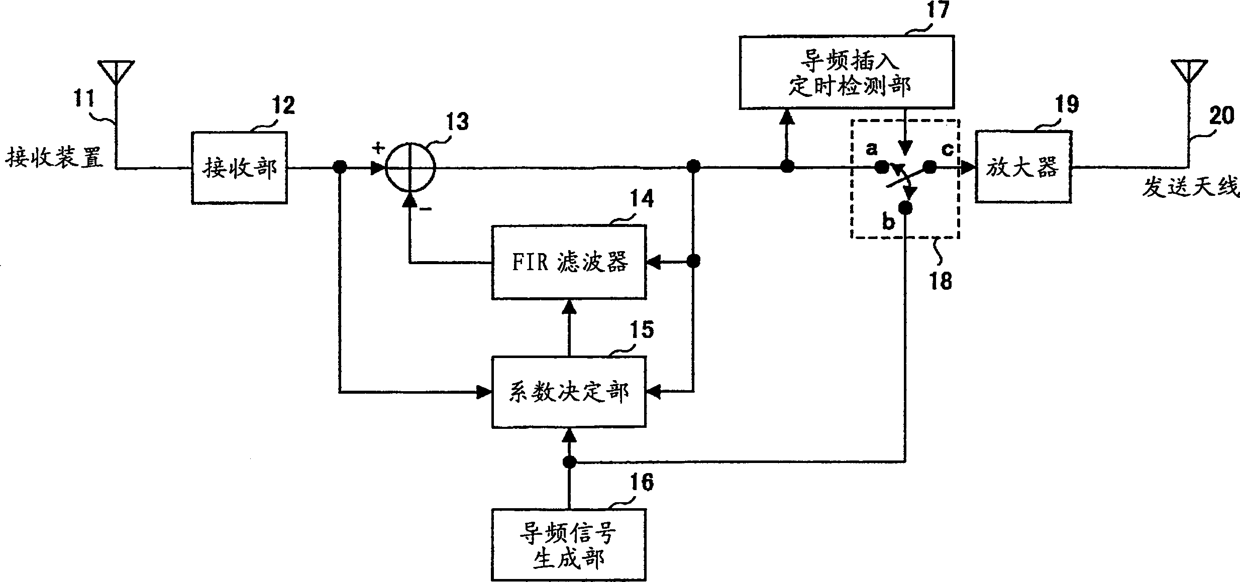
[0055] A wireless relay system including the wireless relay device according to the first embodiment is configured, for example, figure 1 shown. In this figure, the wireless relay system is composed of a transmitting device 1 , a wireless relay device 2 and a receiving device 3 .

[0056] In the present embodiment, the relationship between the transmitter 1 and the receiver 3 is assumed to be a base station (transmitter 1) and a mobile station (receiver 3) of a mobile communication system, and will be described below.

[0057] The signal received by the receiving device 3 includes: a signal received directly from the transmitting device 1 ; and a signal received via the wireless relay device 2 . Once the wireless relay device 2 receives the signal transmitted from the transmitting device 1, it immediately retransmits to the receiving device 3 at the same frequency. In addition, the radio relay system according to this embodiment relays signals using a single-carrier transmi...

no. 2 Embodiment approach

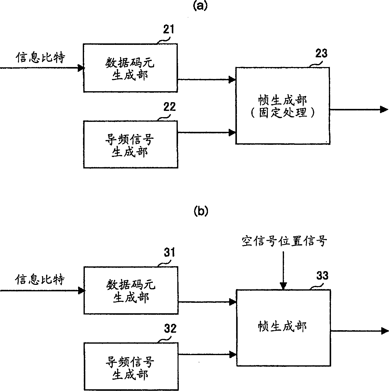
[0078] In a system that performs OFDM communication, it is not necessary to use all the transmitted signals at a certain time as null signals, but only a certain part of the symbols of the subcarriers may be used as null signals.

[0079] Figure 5 is a diagram showing a configuration example of a wireless relay device according to the second embodiment, Image 6 It is a diagram showing an example of the structure of a transmission frame generated by the transmission frame generation unit of the transmission device in this embodiment.

[0080] Figure 5 The shown wireless relay device is configured as, in figure 2 In addition to the structure of the wireless repeater of the first embodiment shown, an FFT section 51 for performing FFT processing on received signals and an IFFT section 59 for performing IFFT processing on transmitted signals are added, and they have 50 subcarriers corresponding to each subcarrier. 1 ~50 n . Hereinafter, only differences from the first embo...

no. 3 Embodiment approach

[0089] In the above-mentioned embodiment, the description was made assuming that the power amplification ratio of each subcarrier is constant when OFDM transmission is used, but in this embodiment, in order to obtain better communication quality, the The power amplification ratio of the wireless repeater. That is, the wireless relay device of this embodiment has a function of controlling the power amplification factor for each subcarrier.

[0090] As shown in FIG. 7, the wireless relay device according to this embodiment is configured such that Figure 5 On the basis of the structure of the illustrated embodiment, the following parts are added: a transmission device insertion pilot signal generation unit 62, which generates a transmission device insertion pilot signal inserted by the transmission device; a channel estimation unit 63; a power control amount determination unit 64; a multiplier 69. Multiply the power control amount determined by the power control amount determin...


PUM


Abstract

A wireless relay system for relaying a radio signal transmitted from a first wireless station to a second wireless station via a wireless relay apparatus is disclosed. The wireless relay system includes a relay control part for receiving transmission symbols transmitted from the first wireless station and refraining from relaying a portion of the symbols, a pilot signal transmission part for transmitting a pilot signal that is inserted into a section of the portion of the transmission symbols, a coupling loop interference wave estimation part for receiving the pilot signal and estimating a coupling loop interference wave based on the pilot signal, and a coupling loop interference wave cancellation part for subtracting the estimated coupling loop interference wave from a reception signal.

Description

technical field [0001] The invention relates to a wireless relay system, a wireless relay device and a wireless relay method for performing wireless communication with a transmitting and receiving device through one or more wireless relay devices. Background technique [0002] In recent years, research has been conducted on a method of relaying between a transmitting device and a receiving device using a wireless relay device (=repeater) using the same frequency band. Oscillations generated by the interference wave from the coupling loop of the receiving antenna are important. That is, deterioration of characteristics due to occurrence of oscillation becomes a big problem. [0003] Also, these relay methods are mainly studied and used in broadcasting, so the suppression of coupling loop interference waves is relatively easy. However, as in the mobile communication system, when it is assumed that the wireless relay device is located in the same environment (not on iron towe...

Claims


Application Information

Patent Timeline
Patent Type & Authority Applications(China)
IPC IPC(8): H04J11/00H04B7/015H04B7/15H04B7/155H04B7/26H04J99/00
CPCH04L5/0032H04B7/15585H04L25/0226H04L5/0048H04L5/0023H04L27/2602G07F17/32A63F13/90A63F2250/14
Inventor 藤井启正须田博人田中哲
Owner NTT DOCOMO INC
Learn More