Punching mould appts.and metal punching method

A technology for stamping dies and metal plates, which is applied in the field of metal stamping processing, and can solve problems such as inability to confirm

Inactive Publication Date: 2005-08-31
PANASONIC CORP +1
View PDF1 Cites 13 Cited by
  • Summary
  • Abstract
  • Description
  • Claims
  • Application Information

AI Technical Summary

Problems solved by technology

In addition, the technology disclosed in Patent Document 1 does not presuppose the use of water-based lubricating fluids like the present invention, and is not a technology that solves the problems associated with the use of water-based lubricating fluids.
Therefore, the technology described in Patent Document 1 is a technology that cannot at all confirm the necessity of storing the lubricating liquid in the concave portion of the elastic member that is indispensable in the operation of the stripper plate or the ejector pin, or preventing it from flowing in (see Patent Document 1). Document 1 [0017] paragraph, figure 1 , figure 2 )

Method used


Image

  • Punching mould appts.and metal punching method
  • Punching mould appts.and metal punching method
  • Punching mould appts.and metal punching method

Examples


Embodiment approach 1

[0034] As described in the background art, the thin metal plate also goes through the preliminary forming process, the punching and deburring process, and reaches the flattening process.

[0035] This press die device for heat exchange fins is composed of an upper die and a lower die that are openably and closably provided, and a die plate (not shown) that constitutes the upper die holds a die for flattening (not shown). ).

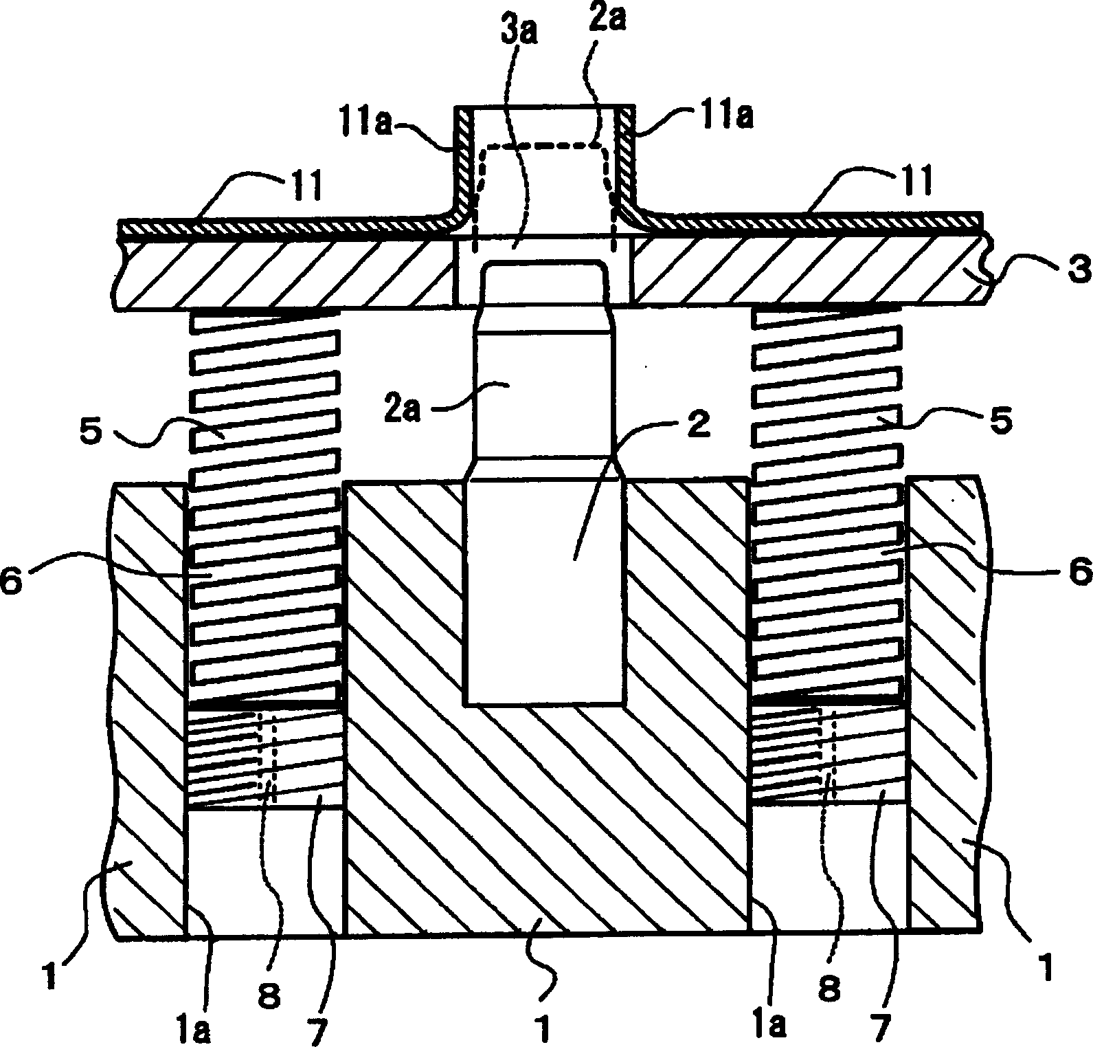
[0036]On the other hand, a flattening punch 2 is fixed to the punch plate 1 constituting the lower die. Above the punch connecting plate 1, a stripper plate 3 is provided at a certain distance from the connecting plate 1. The stripper plate 3 is elastically supported by a spring (coil spring 5) as an elastic member. The stripper plate 3 is provided with a penetration hole 3a through which the head end 2a of the flattening punch 2 can pass, and the head end 2a of the flattening punch 2 is in a state in which no load is applied to the stripper plate 3. T...

Embodiment approach 2

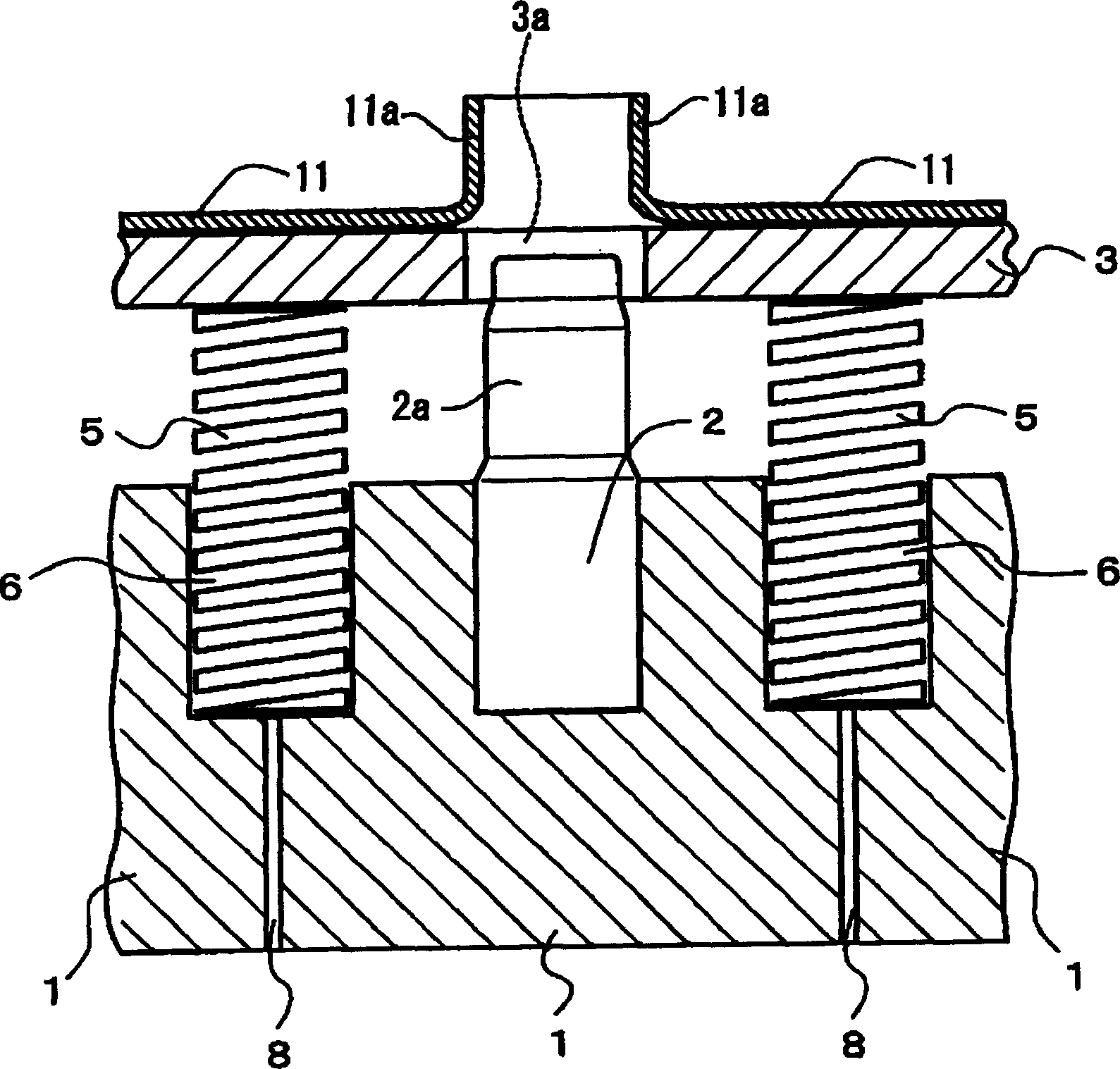
[0050] figure 2 Embodiment 2 which is different from Embodiment 1 described above is shown. In this Embodiment 2, with figure 1 Unlike the first embodiment shown, the concave portion 6 for accommodating the spring 5 is formed as a bottomed hole formed on the upper surface of the punch tab 1 . In addition, a discharge passage 8 for discharging the lubricating liquid is provided through the punch adapter plate 1 from the lower surface of the punch adapter plate 1 to the recessed portion 6, and is provided with the punch adapter plate 1. figure 1 In the same manner as in the illustrated embodiment 1, the lubricating liquid that has flowed into the recessed portion 6 is discharged from the discharge passage 8 . Other structures are due to figure 1 Since Embodiment 1 shown is the same, the same number is used for the same member, and the description is abbreviate|omitted.

Embodiment approach 3

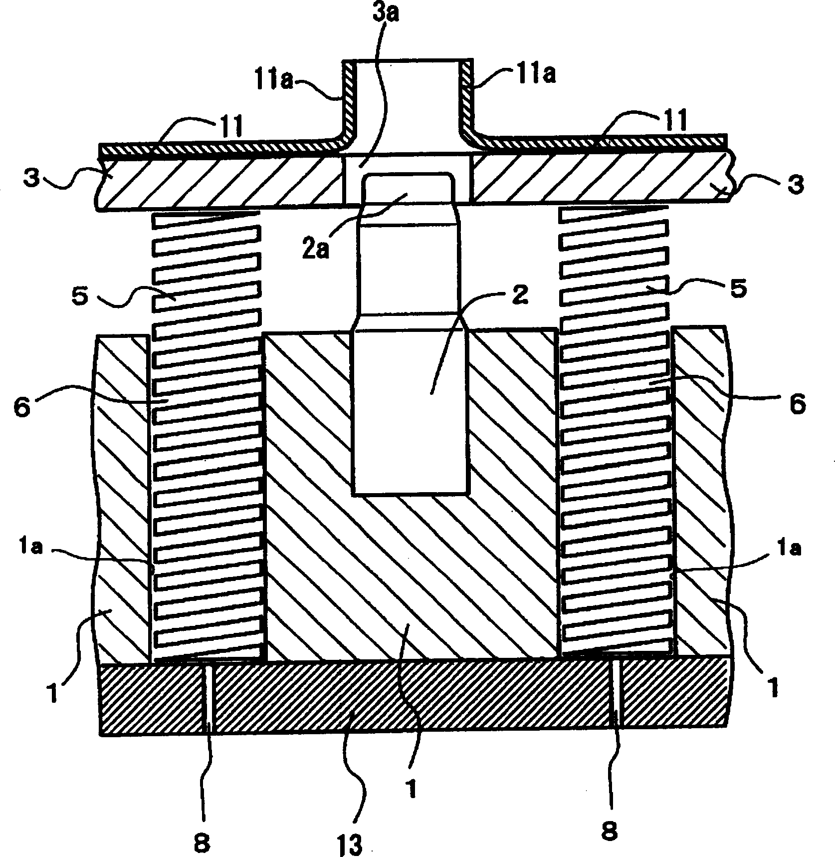
[0052] image 3 Embodiment 3, which is different from the above-described embodiment, is shown. In the third embodiment, the concave portion 6 for accommodating the spring 5 is constituted by the inner side surface of the through hole formed in the punch adapter plate 1 and the upper surface of the support plate 13 arranged on the lower side of the punch adapter plate 1 . Further, the discharge passage 8 communicating with the recessed portion 6 is formed through the support plate 13 , so that the lubricating liquid flowing into the recessed portion 6 is discharged from the discharge passage 8 as in the above-described embodiment. Since other structures are the same as those of the above-described embodiment, the same reference numerals are used for the same members, and the description thereof will be omitted.


PUM


Abstract

The press die device has a discharge passage (8) to discharge aqueous lubricant liquid flowing into a recessed part (6) to store at least a part of a resilient member (5), to the outside of the recessed part (6), and even when the aqueous lubricant liquid enters the recessed part (6), the aqueous lubricant liquid can be discharged outside the recessed part (6) from the discharge passage (8).To provide a press die device capable of suppressing corrosion of a resilient member and decomposition of liquid lubricant on a die by preventing unnecessary liquid lubricant from staying on a die member if aqueous liquid lubricant is used for pressing.

Description

technical field [0001] The present invention relates to a stamping die device and a metal stamping process method used in stamping processes such as plastic working and punching of metal plates, and particularly relates to a stamping process used in the manufacture of heat exchanging fins constituting heat exchangers such as air conditioners. A die device and a metal stamping method using the die device. Background technique [0002] Conventionally, heat exchanging fins used in heat exchangers such as automobiles and household air conditioners use Figure 7 (a) It is produced by a series of press working as exemplified. The stamping process mainly includes a preliminary forming process for making the metal plate to be processed such as aluminum easy to process, a punching and deburring process for punching holes in the preformed metal plate and performing deburring, and forming the formed metal plate. The bell mouth process is formed by bending the head end of the drill hol...

Claims


Application Information

Patent Timeline
Patent Type & Authority Applications(China)
IPC IPC(8): B21D37/18B21D22/02B21D37/10B21D45/08B21J13/02
CPCE04G21/3204E04G21/329
Inventor 村田敬一荫山幸俊
Owner PANASONIC CORP
Why Eureka
Try Eureka