Backlighting device for an information display element of a portable object

A backlight device and information display technology, applied in the direction of visual time indicating device, identification device, optical element, etc., can solve the problems of high cost and complicated operation

Active Publication Date: 2005-08-31
ETA SA MFG HORLOGERE SUISSE
View PDF1 Cites 19 Cited by
  • Summary
  • Abstract
  • Description
  • Claims
  • Application Information

AI Technical Summary

Problems solved by technology

To obtain such a compensation film, all said operations are complicated and costly, which is a drawback

Method used


Image

  • Backlighting device for an information display element of a portable object
  • Backlighting device for an information display element of a portable object
  • Backlighting device for an information display element of a portable object

Examples


Embodiment Construction

[0025] In the following description, those elements of the backlight device known to those skilled in the art will not be described in detail. Said embodiments relate in particular to a backlight arrangement for an information display element of a watch. The display element may be a liquid crystal translucent screen or a watch face with areas transparent to visible light.

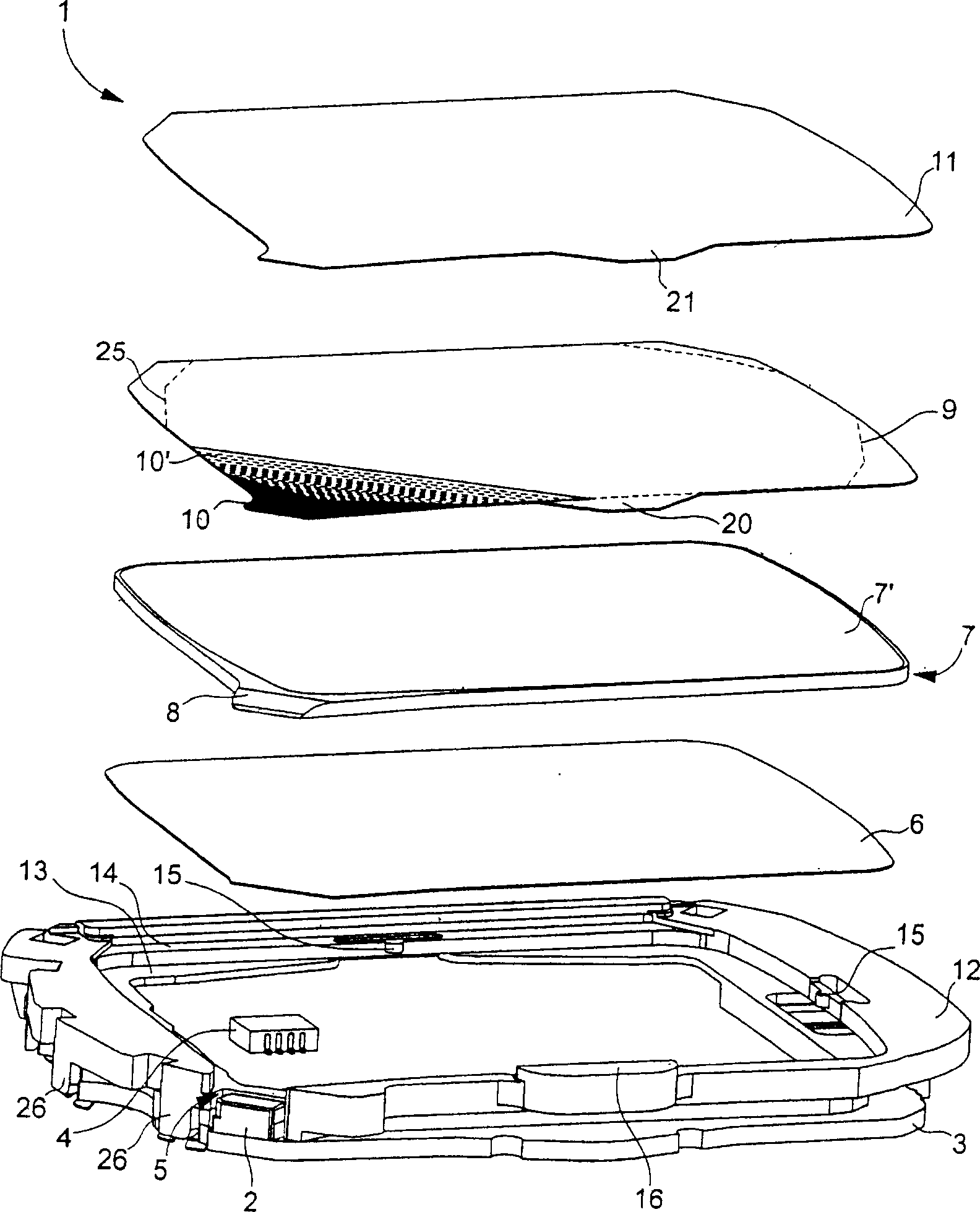
[0026] figure 1 A three-dimensional exploded view of an embodiment of a backlight device 1 suitable for a watch is shown. In this embodiment, the backlight device 1 for an information display element (not shown) firstly comprises a printed circuit board 3, on which a light source—such as a vertically illuminated LED 2—and at least one electronic component are fixed. 4. The light-emitting diodes are powered by a power source (not shown), such as a battery or accumulator, which is electrically connected to the printed circuit board 3 .

[0027] A frame-like, preferably white or black crosspiece 12 made of...


PUM


Abstract

The backlighting device ( 1 ) enables an information display element of a portable object such as a wristwatch to be illuminated from the back. This device comprises a light guide plate ( 7 ) having a front face and a rear face, a light reflector ( 6 ) located on the rear face of the light guide plate, a light diffuser film ( 9 ) and a rectifier film ( 11 ) located on the front face of the light guide plate and a source of visible light ( 2 ). This light source, such as a light emitting diode ( 2 ), feeds light beams to the edge of the light guide plate, which spread in the light guide plate between its two faces. A layer, such as a diffuser film, has a zone ( 10 ') with opacity decreasing from a limit ( 25 ) located close to the boundary area of the light guide plate, which receives the light beams of the light source, in order to attenuate the intensity of the light crossing said zone. This zone with decreasing opacity is, for example, a shading white or black dye disposed on the diffuser film.

Description

technical field [0001] The present invention relates to a backlighting device for an information display element of a portable object such as a watch. The backlight device includes a light guide plate with a front side and a back side, a light reflector on the back side of the light guide plate, and a visible light source. The visible light source provides a light beam at the edge or boundary of the guide plate. These light beams travel within the light guide plate between its two faces to be directed to illuminate a display screen located above the front face of the guide plate. The device also includes a layer disposed opposite the rear of the display element of the portable object from a side of the front of the guide plate. Said layer also has at least one region having a partial opacity that gradually decreases from a boundary near a boundary region where the guide plate receives the light beam of the light source. This attenuates the light intensity passing through th...

Claims


Application Information

Patent Timeline
Patent Type & Authority Applications(China)
IPC IPC(8): G04G9/00F21V8/00F21Y101/02G02F1/13357G04G99/00
CPCG02F1/133615G02B6/0018G02B6/0061G02B6/0051G02F1/1335B82Y40/00
Inventor F·昂列F·克洛普芬斯滕
Owner ETA SA MFG HORLOGERE SUISSE
Why Eureka
Try Eureka