Non-reciprocal circuit element

A technology for circuit components and components, applied in the field of non-reciprocal circuit components, can solve the problems of poor performance, troublesome assembly operations, and poor productivity, and achieve the effects of small position shift, good assembly, and good productivity.

Inactive Publication Date: 2005-08-31
ALPS ALPINE CO LTD
View PDF1 Cites 5 Cited by
  • Summary
  • Abstract
  • Description
  • Claims
  • Application Information

AI Technical Summary

Problems solved by technology

[0016] In conventional nonreciprocal circuit elements, since the first capacitor C1, the second capacitor C2, the third capacitor C3, and the capacitor R are arranged in a state in which the flat plate portion (thickness direction) is parallel to the bottom plate 53a, there is a problem of lateral enlargement. The problem
[0017] In addition, since the first central conductor 56, the second central conductor 57, and the third central conductor 58 are bent so as to surround the ferrite member 55, the work is troublesome. 56. The position of the second center conductor 57 and the third center conductor 58 is shifted, resulting in poor performance
[0018] In addition, since the ferrite member 55 combining the first center conductor 56, the second center conductor 57, and the third center conductor 58, and the respective first capacitor C1, second capacitor C2, and third capacitor C3 are housed in the resin Inside the housing 54, there are problems such as cumbersome assembly work, poor productivity, and high cost.
[0019] In addition, since the first capacitor C1, the second capacitor C2, and the third capacitor 3 must be accommodated in the resin case 54, the first central conductor 56, the capacitors C1, C2, and C3 must be soldered in a narrow space. The channel portions 56b, 57b, and 58b of the second center conductor 57 and the third center conductor 58 have the problems of troublesome work, poor productivity, and high cost.

Method used


Image

  • Non-reciprocal circuit element
  • Non-reciprocal circuit element
  • Non-reciprocal circuit element

Examples


Embodiment Construction

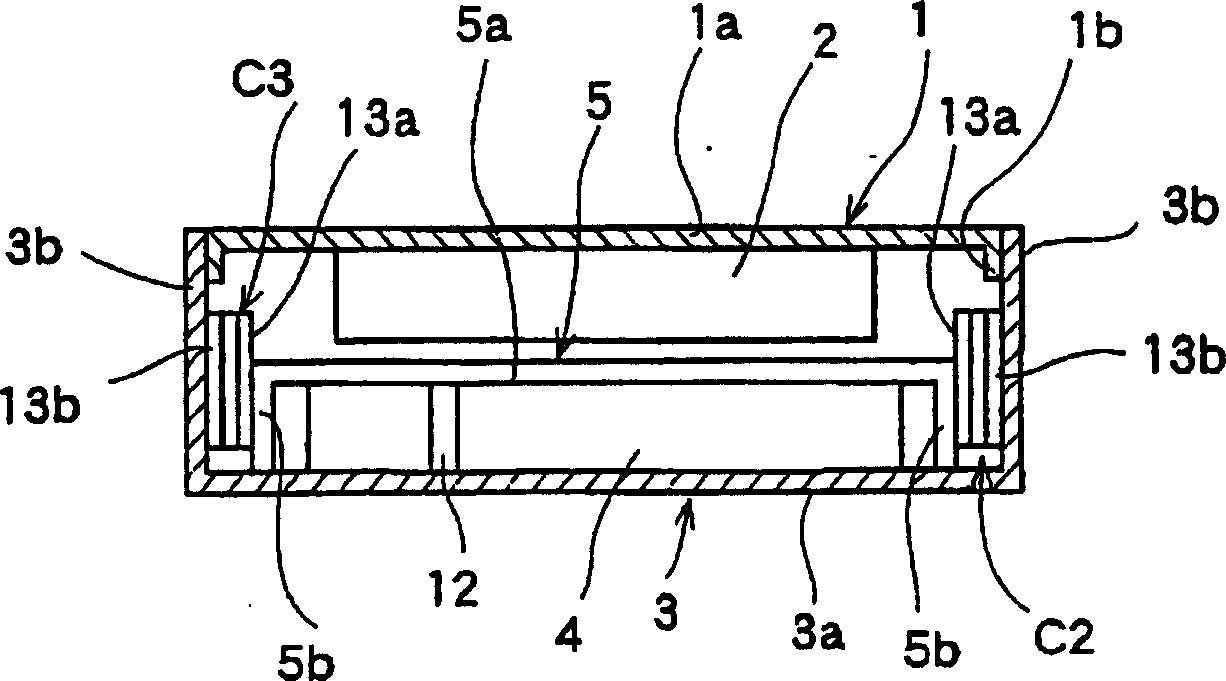
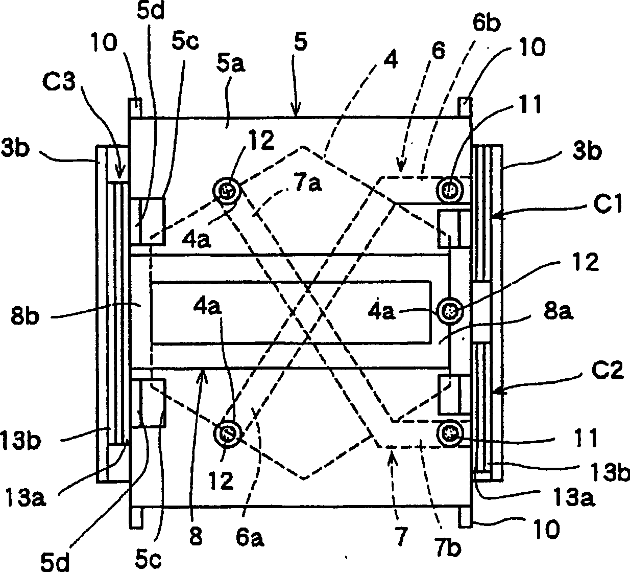
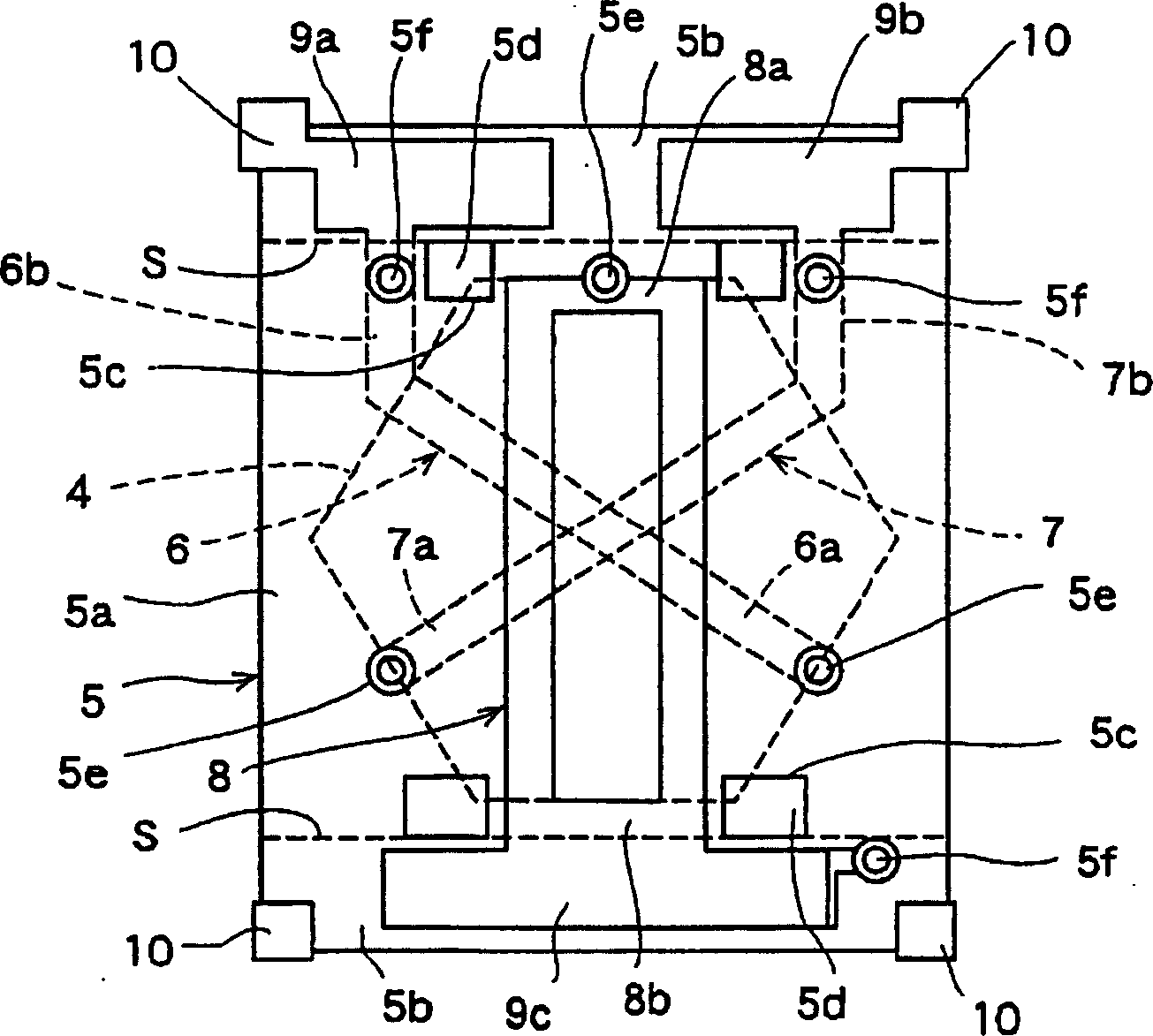
[0046] First, the drawings illustrating the nonreciprocal circuit element of the present invention, figure 1 It is a sectional view of main parts of the nonreciprocal circuit element of the present invention, figure 2 It is a plan view showing a state in which the first yoke and the magnet of the nonreciprocal circuit element of the present invention are removed, image 3 It is a developed view showing the dielectric body of the nonreciprocal circuit element of the present invention, Figure 4 It is a developed view of a state in which a capacitor is mounted on a dielectric body of the nonreciprocal circuit element of the present invention, Figure 5 It is a perspective view of the dielectric body of the nonreciprocal circuit element of this invention.

[0047] Below, refer to Figure 1 to Figure 5 , to describe the structure when the nonreciprocal circuit element of the present invention is used in an isolator, a U-shaped first yoke 1 composed of a box-shaped magnetic pl...


PUM


Abstract

A non-reciprocal circuit element includes a bendable dielectric which is made of a laminated plate in which insulating thin plates are laminated, first to third central conductors which are formed at different laminated locations of the dielectric to be integrated with the dielectric and which are disposed such that parts the first to third central conductors cross each other in a vertical direction, and capacitors disposed between the dielectric and a yoke. The capacitors are disposed between side plates of the yoke and bent portions bent from a base portion of the dielectric. Thus, flat portions (thickness direction) of the capacitors are provided upright with respect to a lower plate.

Description

technical field [0001] The present invention relates to a non-reciprocal circuit element composed of an isolator or a circulator used in a duplexer such as an antenna and a manufacturing method thereof. Background technique [0002] Image 6 It is an exploded perspective view of a conventional nonreciprocal circuit element. Below, refer to Image 6 The conventional nonreciprocal circuit element is described. The first yoke 51 made of a box-shaped magnetic plate (iron plate, etc.) is formed in a box shape, and a disk-shaped magnet 52 is attached to the first yoke with an adhesive or the like inside it. 51 on. [0003] The second yoke 53 made of a magnetic plate (iron plate, etc.) has a bottom plate 53a and two side plates 53b bent upward from two opposing sides of the bottom plate 53a. The yoke 51 is combined to form a closed magnetic circuit. [0004] A box-shaped resin case 54 made of a synthetic resin molded product has a circular through-hole 54b provided in the central...

Claims


Application Information

Patent Timeline
Patent Type & Authority Applications(China)
IPC IPC(8): H01P1/36H01P1/32H01P1/383
CPCH01P1/32
Inventor 清水祐一
Owner ALPS ALPINE CO LTD
Why Eureka
Try Eureka