
Wireless device having antenna

A technology of wireless devices and antenna oscillators, applied to antenna support/installation devices, devices that enable antennas to work in different bands at the same time, antennas, etc., can solve problems such as high-efficiency adjustments

Inactive Publication Date: 2005-08-31
PANASONIC CORP
View PDF1 Cites 25 Cited by
  • Summary
  • Abstract
  • Description
  • Claims
  • Application Information

AI Technical Summary

Problems solved by technology

As a result, it is difficult to efficiently adjust only one resonance frequency independently

Method used


Image

  • Wireless device having antenna
  • Wireless device having antenna
  • Wireless device having antenna

Examples


Embodiment Construction

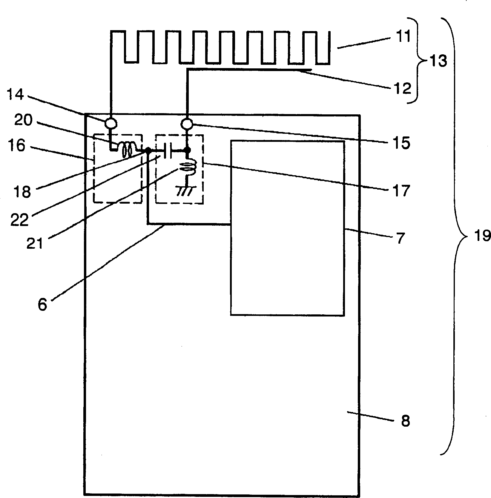
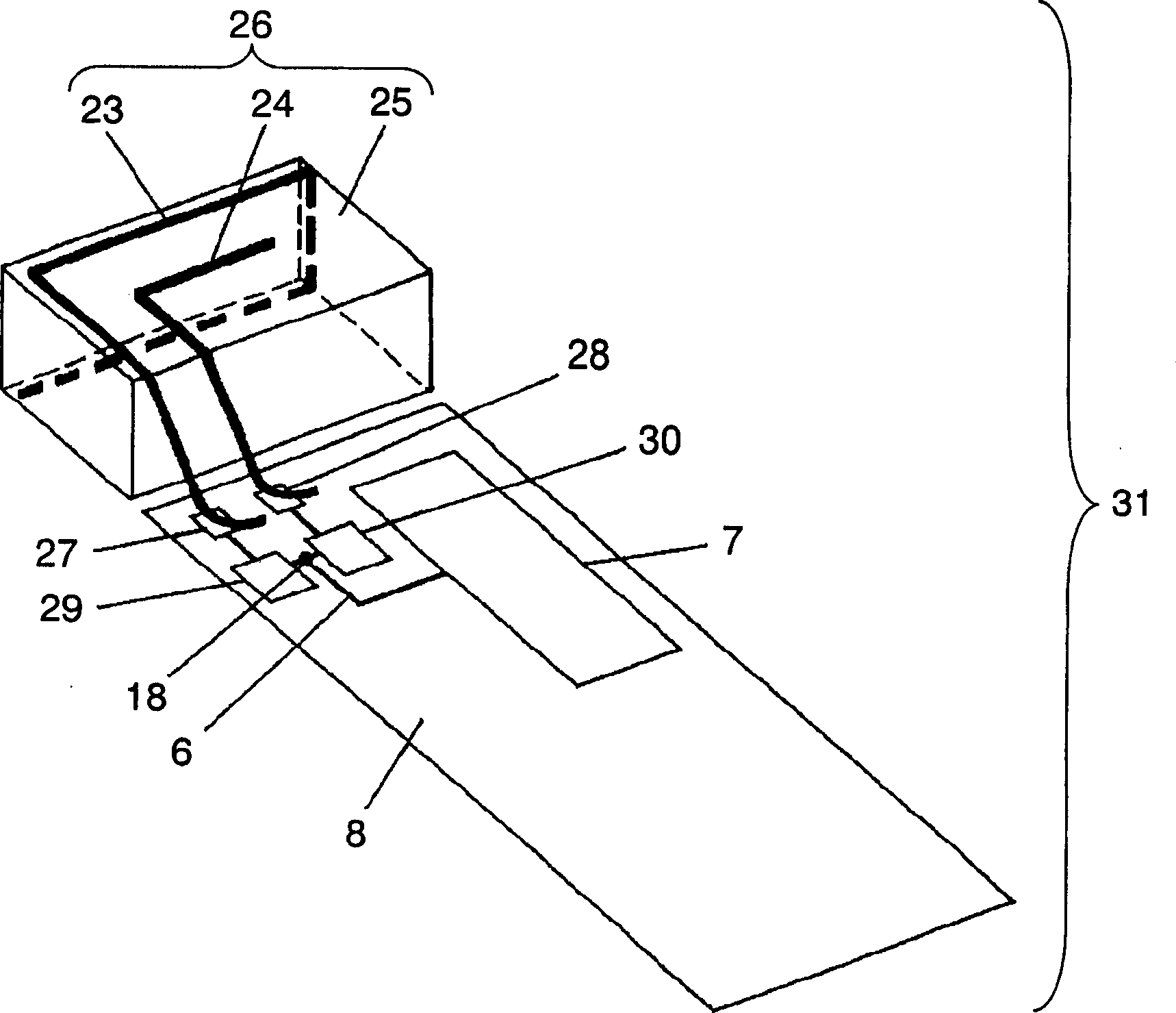
[0027] Hereinafter, embodiments of the present invention will be described with reference to the drawings.

[0028] figure 1 is a diagram schematically showing a wireless device in an embodiment of the present invention, figure 2 It is a perspective view schematically showing a wireless device according to an embodiment of the present invention equipped with an antenna including an antenna element made of an elastic metal material and an insulating resin.

[0029] The wireless device 19 of the present invention has the following structure. That is, it includes: the first antenna element 11, resonating at the first frequency; the first feed point 14, connected to the first antenna element 11, and configured on the bottom board 8 in the wireless device 19; the first matching circuit 16, one end connected to the first feed point 14; the second antenna element 12 resonates at a frequency higher than the first frequency; the second feed point 15 is connected to the second anten...


PUM


Abstract

A wireless device includes a first antenna element resonating with a first frequency, a first feeding point coupled to the first antenna element and disposed on a ground plane in the wireless device, a first matching circuit of which first end is coupled to the first feeding point, a second antenna element resonating a second frequency higher than the first frequency, a second feeding point coupled to the second antenna element and disposed on the ground plane, a second matching circuit of which one end is coupled to the second feeding point, and a radio circuit coupled via a transmission line to a common connection point (18) shared by respective second ends of the first and second matching circuits.

Description

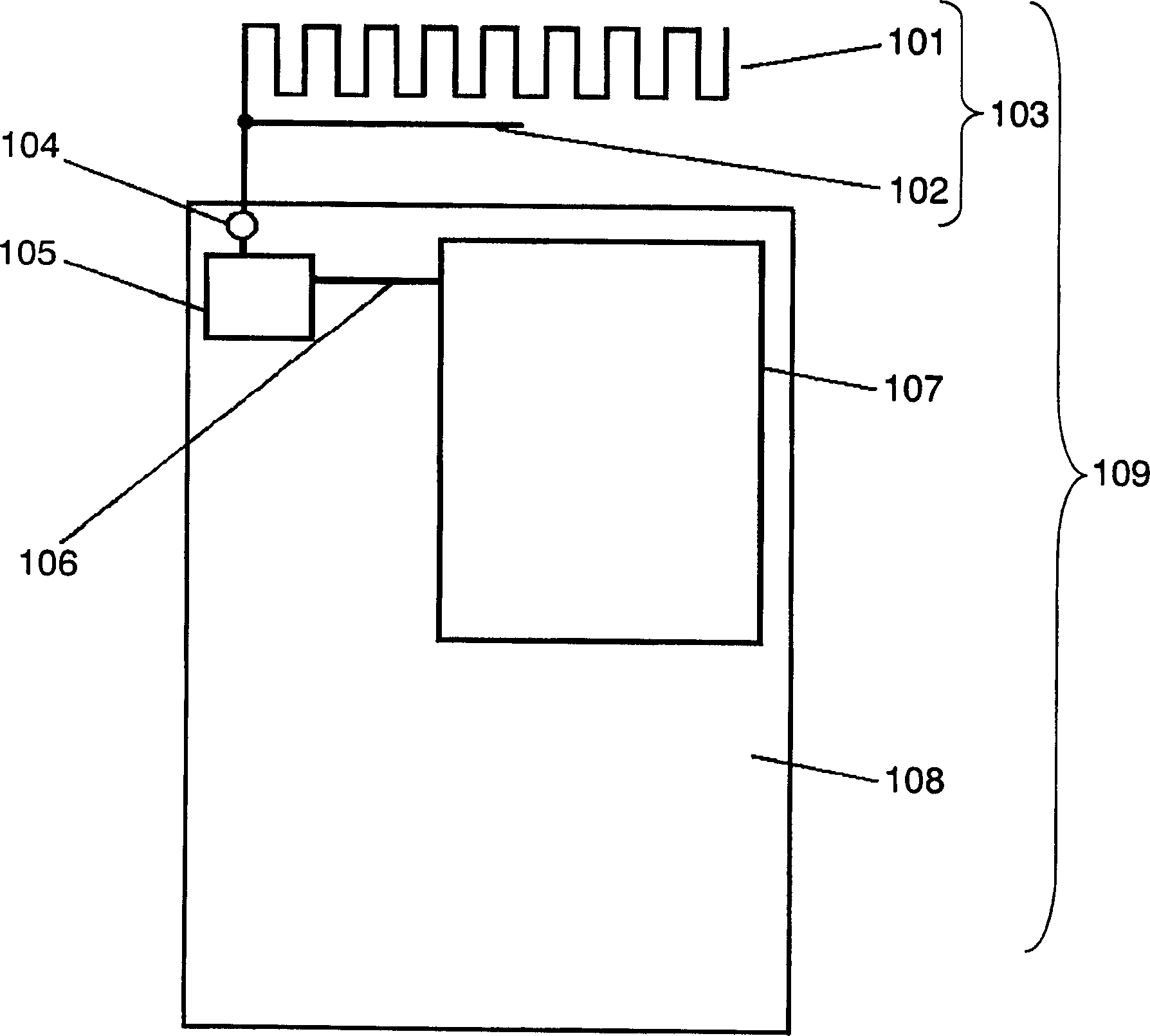
technical field [0001] The present invention relates to a wireless device equipped with an antenna. In particular, it relates to wireless devices used for mobile communications such as mobile phones. Background technique [0002] In recent years, in mobile communication including mobile phones, data communication services for voice calls, text, and video are diversified, and high-performance wireless devices are required. In particular, the performance of an antenna serving as a portal for transmitting and receiving radio waves is one of the important factors affecting the performance of a wireless device, and therefore a wireless device equipped with a high-performance antenna is eagerly desired. [0003] use image 3 Such a conventional wireless device will be described. image 3 It is a diagram schematically showing a conventional wireless device equipped with an antenna. [0004] exist image 3 In , the antenna 103 and the bottom plate 108 are arranged side by side. T...

Claims


Application Information

Patent Timeline
Patent Type & Authority Applications(China)
IPC IPC(8): H01Q21/28H01Q1/24H01Q1/38H01Q1/52H01Q5/00H01Q9/42H01Q21/30
CPCH01Q1/243H01Q1/38H01Q21/30H01Q5/40H01Q9/42H01Q5/0072
Inventor 高木直志佐藤佑己
Owner PANASONIC CORP
Learn More