Tension constant compensation device

A compensation device, constant tension technology, applied in the direction of overhead lines, etc., can solve the problems of high cost, heavy weight, and inability to popularize and use

Inactive Publication Date: 2005-09-07
YANGZHOU DONGFANG HANGER FRAME CO LTD
View PDF0 Cites 19 Cited by
  • Summary
  • Abstract
  • Description
  • Claims
  • Application Information

AI Technical Summary

Problems solved by technology

[0004] 1. A compensation device using a simple cylindrical helical compression spring - because the spring has the characteristic that the force is proportional to the stroke, this compensation device cannot guarantee the constant tension of the cable;
[0005] 2. The compensation device made of disc springs - due to ...

Method used


Image

  • Tension constant compensation device
  • Tension constant compensation device
  • Tension constant compensation device

Examples


Embodiment 1

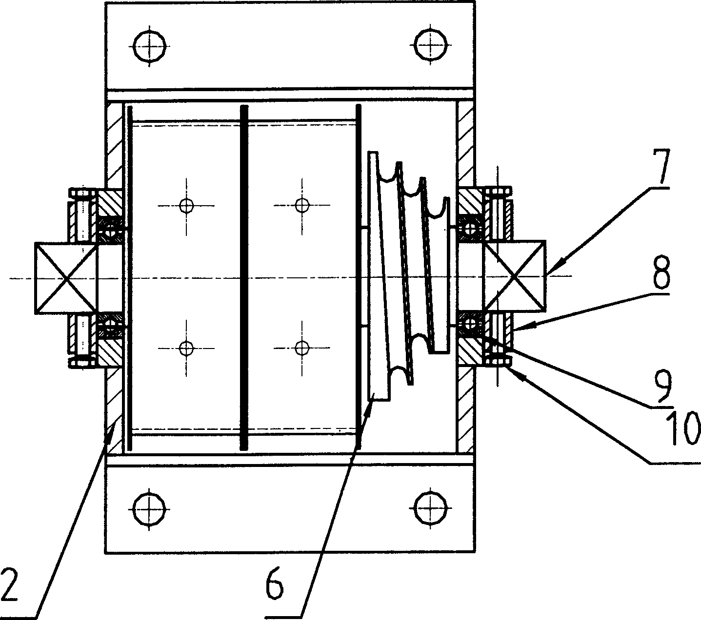
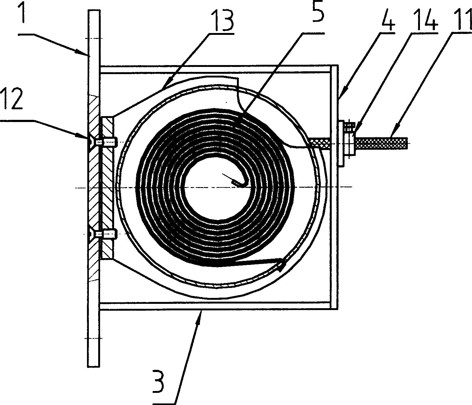
[0036] The constant tension compensation device of this embodiment is as figure 1 , figure 2 As shown, the main components are installation connecting plate 1, end plate 2, side plate 3, cover plate 4, variable torque plane scroll spring 5, involute sheave 6, main shaft 7, end cover 8, bearing 9, locking bolt 10. Wire rope 11, connecting bolt 12, plane scroll spring box 13, wire rope locking device 14, etc. Wherein the connecting plate 1, the end plate 2, the side plate 3 and the cover plate 4 are combined into a closed box base body. Bearings 9 on both sides of the box base body support the main shaft 7, and two linear variable torque flat scroll springs 5 ​​located in the flat scroll spring box 13 are installed on the main shaft 7. The outer end of the linear variable torque plane scroll spring 5 is relatively fixed with the box base, and the inner end is connected with the main shaft 7 through a hook. Multi-turn involute sheave 6 through key (see Figure 9 ) is connect...

Embodiment 2

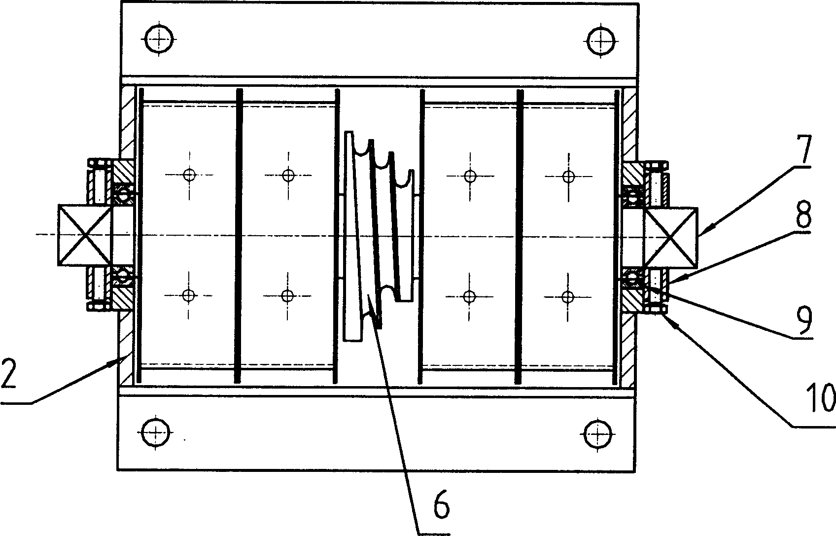
[0046] The constant tension compensation device of this embodiment is as image 3 and Figure 4 As shown, the basic structure is the same as that of Embodiment 1, except that it contains two pairs (in fact, any even number of more than two) variable torque plane scroll spring groups 5, which are symmetrically installed on the involute sheave 6 on both sides.

Embodiment 3

[0048] The constant tension compensation device of this embodiment is as Figure 5 and Figure 6 As shown, its basic structure is the same as that of Embodiment 1, the difference is that the constant torque planar scroll spring group 5 and the helical sheave 6 (or fixed chute sheave) are used in combination, so it can also meet the requirement of constant tension output. The key connection structure of spiral sheave 6 sees Figure 10 .


PUM


Abstract

The invention relates the constant tension compensation equipment, and belongs to the electrolyzed railway power supply technology field. The equipment comprises the spring on the substrate, and the said spring is the constant turning rule or linear changeable turning rule plane turbination spring with one end fixed opposite to the substrate and the other to the main shaft; the said main shaft is supported on the substrate and the shaft is rigidly set with the crown chute, the screw chute, the linear chute that are enwound by the steel wire lines. When the stress cable and the contacting wire lead the length change as the environmental temperature changing, the matching group of the springs and the chutes can be compensatively adjusted through the tension of the springs and maintain the constant tension on the stress cable and the contacting wires so as to meet the demand of the electrolyzed railway engineering. The invention has the strong points of tight structure, small volume, light weight and convenient equipment.

Description

technical field [0001] The invention relates to a device for compensating the length change of catenary cables and contact wires (hereinafter referred to as cables) caused by environmental temperature changes and keeping the tension constant, belonging to the technical field of electrified railway power supply. Background technique [0002] According to the applicant's knowledge, at present, the tension compensation device widely used in the electrified railway catenary is composed of concrete or cast iron weights and pulley blocks. Although this compensating device has the advantage of simple structure, it has the disadvantages of large volume, heavy weight, unattractive appearance, and easy swing and collision in strong wind. In addition, due to the need to use auxiliary structures for support, guidance and protection, its installation and maintenance costs are high. Especially in the case of electrified catenary transformation under low and narrow clearance conditions su...

Claims


Application Information

Patent Timeline
IPC IPC(8): B60M1/26
Inventor 吴利群帖荣俊
Owner YANGZHOU DONGFANG HANGER FRAME CO LTD
Why Eureka
Try Eureka