

Bridge ship loader-unloader
A loading and unloading mechanism and bridge-type technology, which is applied in the directions of loading/unloading, transportation and packaging, etc., can solve problems such as belt deviation, affecting transportation operations, and affecting the working distance of ship unloaders, so as to reduce the cost and simplify the process.
- Summary
- Abstract
- Description
- Claims
- Application Information
AI Technical Summary
Problems solved by technology
Method used
Image

Examples
Embodiment Construction
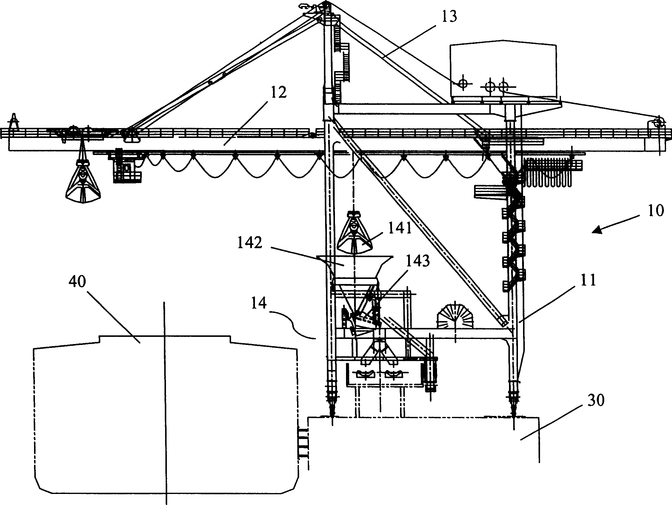
[0027] In order to facilitate the understanding of the ship loading and unloading machine of the present invention, please first combine figure 1 As shown, a simple description is made to the structure of the traditional ship unloader:
[0028] figure 1 Among them, the ship unloader 10 includes a derrick 11, a girder 12, a hanger 13, and a loading and unloading mechanism 14,
[0029] The girder 12 is horizontally arranged on the derrick 11, the hanger 13 is arranged on the derrick 11 and connected with the girder 12, the loading and unloading mechanism 14 is located under the girder 12 and the derrick 11,
[0030] The loading and unloading mechanism 14 includes a grab 141 , a funnel 142 , and a feeder 143 . The grab 141 is slidably arranged on the girder 12 , and the outlet of the funnel 142 is connected to the feeder 143 .
[0031] figure 1 Among them, 30 is the wharf, and 40 is the ship that needs to unload materials.
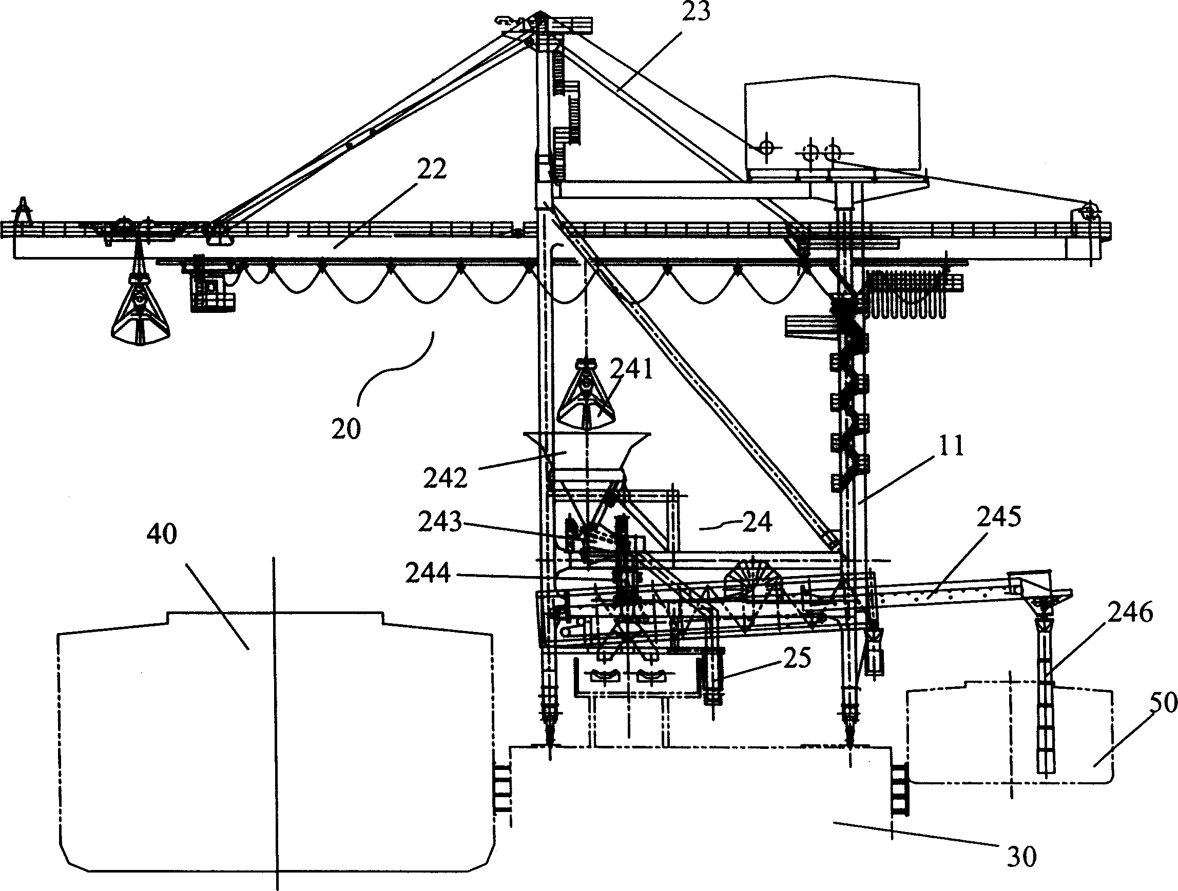
[0032] see again figure 2 as shown,
[0033] The...
PUM
 Abstract
Description
Claims
Application Information