Standard time signal receiving time device and decoding method of time code signal

A technology of standard radio waves and clock devices, applied in synchronizing devices, electronic timers, electromechanical clocks, etc., can solve the problems of increased calculation amount, increased product cost, and increased power consumption.

Inactive Publication Date: 2005-09-07
OKI ELECTRIC IND CO LTD
View PDF1 Cites 5 Cited by
  • Summary
  • Abstract
  • Description
  • Claims
  • Application Information

AI Technical Summary

Problems solved by technology

However, in the prior art, for example, since the integrated value of the time code signal pulse generated based on the standard radio wave is sampled at regular intervals, additional processing such as code identification is performed, so the calculation becomes complicated and the amount of calculation is increased. increasing trend
Therefore, a radio wave clock that implements trouble countermeasures must have a microcomputer with a strong processing capability. Furthermore, due to the need for increased arithmetic processing to operate through a high-speed clock, the product cost increases and the power consumption increases.

Method used


Image

  • Standard time signal receiving time device and decoding method of time code signal
  • Standard time signal receiving time device and decoding method of time code signal
  • Standard time signal receiving time device and decoding method of time code signal

Examples


Embodiment 1

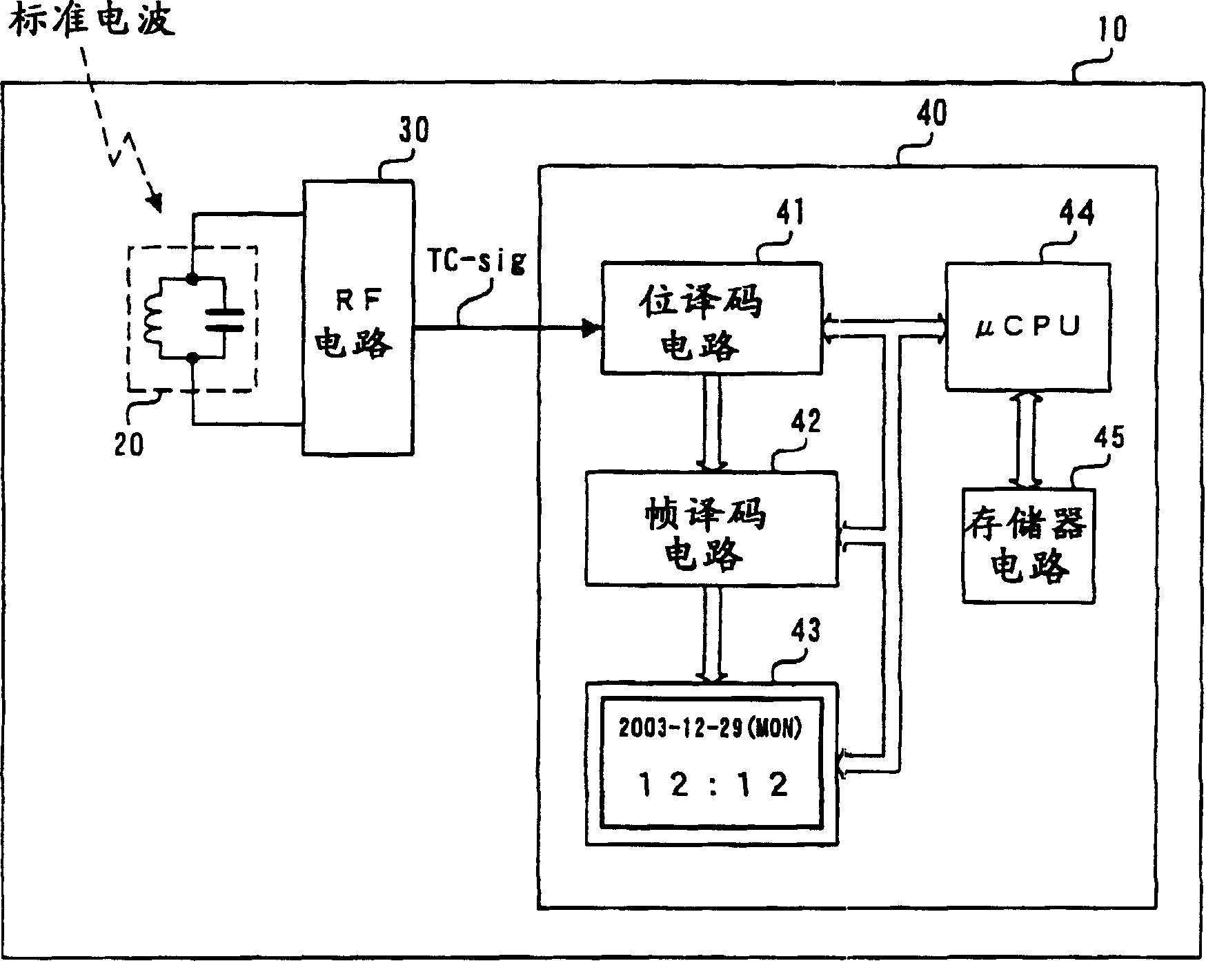
[0041] according to figure 1 The block diagram shown illustrates a first embodiment of the radio controlled clock and time code decoding method of the present invention. The purpose of this embodiment is to achieve correct bit synchronization of the code pulses contained in the time code signal.

[0042] Based on the radio wave clock 10 of this embodiment such as figure 1 As shown, it is mainly composed of an antenna 20 , a high frequency circuit 30 and a main processing circuit 40 . The main processing circuit 40 includes various circuits such as a bit decoding circuit 41 , a frame decoding circuit 42 , a display circuit 43 , a microprocessor 44 and a memory circuit 45 . In addition, although the radio-controlled clock 10 includes other circuits such as a power supply circuit and an operation input circuit, description and description of these circuits are omitted because they are not directly related to the present invention.

[0043] Next, each component of the radio-con...

Embodiment 2

[0058] Next, a second embodiment of the present invention will be described. The configuration of the radio-controlled timepiece of the second embodiment is the same as that of the first embodiment, so description and description of the configuration will be omitted.

[0059] The purpose of this embodiment is to prevent the normal decoding of each code from being hindered by noise mixing or waveform distortion. That is, the purpose of this embodiment is to reliably decode each code of 1 bit included in a time code signal into each code of a binary "0", a binary "1" or an identifier. In addition, as a prerequisite for realizing this embodiment, it is necessary to implement the bit synchronization method described in the first embodiment and to tabulate the sampling data of the time code signal established by the bit synchronization.

[0060] First, use Figure 5 The basic concept of this embodiment will be described. Figure 5 (a) represents the data of binary "0" after samp...

Embodiment 3

[0068] Next, a third embodiment of the present invention will be described. The configuration of the radio-controlled timepiece of the third embodiment is the same as that of the first embodiment, so description and description of the configuration will be omitted. In addition, as a premise for realizing this embodiment, it is assumed that the bit synchronization method described in the first embodiment is implemented, and the sampling data of the time code signal established by bit synchronization is tabulated, and the template pattern of the second embodiment is implemented. Code judgment method (hereinafter referred to as "simple bit pattern judgment").

[0069] Furthermore, the purpose of this embodiment is to prevent the normal decoding of each code from being hindered by noise or waveform distortion, and to further improve the code determination capability described in the second embodiment.

[0070] In the decoding method for simple bit pattern determination of the sec...


PUM


Abstract

In a radio controlled clock and a decoding method of a time code signal, the time code signal can be accurately decoded irrespective of the mixture of noises and the deterioration of a radio wave signal receiving situation, and arithmetic processing is simple. A standard time signal is received and the time code signal superposed on this standard time signal is sampled at an interval of 50 ms and is stored to a memory. The stored sampling data are formed as a list in a data group every one second (20 samples). The plurality of data groups formed as a list are added every each sampling point, and a point for maximizing an increase change of the adding result is set to a synchronizing point of the sampling. Further, the correlation of the sampling data group and a code template pattern is calculated and a code shown by the sampling data group is judged.

Description

technical field [0001] The present invention relates to a standard radio wave receiving clock device (hereinafter referred to as "radio wave clock") for clock correction by receiving a standard radio wave and a decoding method of a time code signal superimposed on the standard radio wave. Background technique [0002] Two domestic transmitters, Kyushu Naga Station and Fukushima Naga Station, operated and managed by the independent corporation National Institute of Communications, constantly transmit time code signals representing Japan Standard Time via long waves. Hereinafter, such long waves are referred to as "standard radio waves". The standard radio waves currently used are two types of waves whose carrier frequencies are 40KHz and 60KHz, and the standard radio waves with different carrier frequencies are transmitted from the above two transmitting stations. [0003] Amplitude modulation is performed on the carrier wave of the standard radio wave by the pulse train of ...

Claims


Application Information

Patent Timeline
Patent Type & Authority Applications(China)
IPC IPC(8): G04G5/00G04R20/00G04R20/12H04L7/00
CPCG04R20/10G04G5/002
Inventor 近藤高行
Owner OKI ELECTRIC IND CO LTD
Why Eureka
Try Eureka